Engine/tranny Mounting angle?

Reading this thread is giving me flashbacks to a process that I would prefer to forget.

Like you guys, my car had the pinion angle at -.5 degrees, Richmond 5 was down 3 degrees. The first issue I found was the floorboard sagging which apparently is a common issue on the fiberglass floor cars, my solution was to use 2 hockey pucks (!) between the BTO crossmember and floorboard to bring it back up level. That gave me the room to raise the tailshaft to just under -2 degrees.

I reworked the bracket with the 2 through bolts on the diff to allow the pinion to go up further and used a thinner bushing - ended up with @1.5 positive at the pinion.

Net result is no vibration and clearance for a 3" driveshaft, 1350 joints at trans, 1330 joint at pinion. The safety loop is close, but I still had to cut out a strip of the tunnel to clear it.

I can get some pics uploaded if it would help anyone.

Phil
 
FWIW, when I had the Richmond in my '79 I had a lot of chatter at the stick shift from driveline vibration. I read a post on another forum, I think it was from Norval, stating that it was desireable to mount the tail end of the trans as high as possible to achieve the most favorable driveline angle (We're talking about a Tremec being installed).
When I had my TKO installed we followed this advice and now the driveline is as good as any car I've driven. The rear (pinion angle) was not adjusted at all. The 'Vette feels like a new car now that vibration issues have been dealt with.
 
Reading this thread is giving me flashbacks to a process that I would prefer to forget.

Like you guys, my car had the pinion angle at -.5 degrees, Richmond 5 was down 3 degrees. The first issue I found was the floorboard sagging which apparently is a common issue on the fiberglass floor cars, my solution was to use 2 hockey pucks (!) between the BTO crossmember and floorboard to bring it back up level. That gave me the room to raise the tailshaft to just under -2 degrees.

I reworked the bracket with the 2 through bolts on the diff to allow the pinion to go up further and used a thinner bushing - ended up with @1.5 positive at the pinion.

Net result is no vibration and clearance for a 3" driveshaft, 1350 joints at trans, 1330 joint at pinion. The safety loop is close, but I still had to cut out a strip of the tunnel to clear it.

I can get some pics uploaded if it would help anyone.

Phil
Pix would be great!

I would really be interested in what you did with the pinion bracket.
 
Reading this thread is giving me flashbacks to a process that I would prefer to forget.

Like you guys, my car had the pinion angle at -.5 degrees, Richmond 5 was down 3 degrees. The first issue I found was the floorboard sagging which apparently is a common issue on the fiberglass floor cars, my solution was to use 2 hockey pucks (!) between the BTO crossmember and floorboard to bring it back up level. That gave me the room to raise the tailshaft to just under -2 degrees.

I reworked the bracket with the 2 through bolts on the diff to allow the pinion to go up further and used a thinner bushing - ended up with @1.5 positive at the pinion.

Net result is no vibration and clearance for a 3" driveshaft, 1350 joints at trans, 1330 joint at pinion. The safety loop is close, but I still had to cut out a strip of the tunnel to clear it.

I can get some pics uploaded if it would help anyone.

Phil
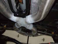
By all means post em up. And I owe ya one. I left some room for a rubber bushing between the tranny and mount. I have a box full of hockey pucks and the thought never crossed my mind. Another quick fix, Thanks! Beats a old piece of tire. :push:

tt
 
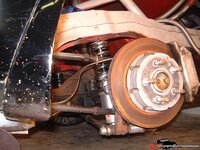
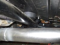
Here are 2 pics I dug up when I was going through the process - I'll go out tonight and get some updated ones and one of the 'professional' hockey puck install.

This shows the modified diff bracket - I just ground off the factory welds on the two bolt reinforcement places, redrilled the front hole on the bracket about 1/2" higher and rewelded the plates. This gives you the ability to push up the diff. Not high tech, but it worked for me. I don't think I had thinned down the bushing yet in this picture.

22449b7e1b839c2d.jpg

Safety loop cutout. For whatever reason the body on my car has always sat slightly off to the driver side which is why I had to clearance for the loop on the passenger side of the tunnel.

22449b7e23e96e4e.jpg

Phil
 
Thanks for the picture.

Now your going to have to post some pix and a description of what you did on the rear suspension. Inquiring minds want to know :bounce:
 
Looks like a guldstrand type setup with the 2 lower camber struts/toe control setup.

Is it a riley/guldstrand one or is it home built?

This is an old steel fabricated one on a race car:
249b810eae67d5.jpg

Details please :D
 
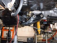
Hockey puck install as promised. I don't have the car on the lift to get a better shot but there is another in about the same place on the other side. I notched the puck to sit at the desired height and have a countersunk machine screw through the top of each into the crossmember. It has worked surprisingly well for a couple of years now.

22449b87879ec031.jpg

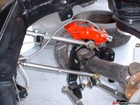
Rear suspension is a Riley Protofab 5 link. I installed it in 2002, it came off an old race car that Howard had. One of the best things I ever did on this car. Old pic here shows the detail the best, I have since gone to Wilwoods and a few other changes in the back.

22449b87918dd5f4.jpg

Phil
 
I remember that one, I wanted to buy it but someone already snagged it (you) and I got a very polite reply from Howard :D "you snooze you loose" Pissed me off to no end ;) LOL
 
I like how you attached the emergency brake cable to the trailing link. I'm trying to solve the same problem with my home made 5-link. In TX you have to have a working parking brake to pass the safety inspection each year.

I also made the mistake of going with the narrow mount Wilwoods which made it damn tough to create a bracket for the caliper and give clearance for the shoe actuator arm.


Thanks - I can't take full credit for the ebrake cable attachment. I called Guldstrand's shop and the man himself explained how they made them work with the 5 links. Very nice guy.

Phil
 
I know, but Guldstrand copied the riley protofab one and his is now cast aluminium.
 
Top