Ok, I'm back on this side project.
Upon testing it turned out relays were creating too much interference.
When the controlleur was outside the box, it worked fine. But as soon as I put it inside, it would start randomly initiating shutdown.
And in general I felt the setup was clumsy.
So I put it in the back burner for a while.
Wise move.
Learned a couple of thing in the meanwhile :
-Getting my first car audio amplifier, I learned the "ampli power" signal it not the actual power the ampli needs, but a mere 'signal' 12V to trigger on the ampli. Yep, I'm that noob.
-Then I realised the screen wouldn't be linked to this module, the screen is on ACC and that's it. I need it for the rearview camera anyway... so less current to drive.
-Top of that, I figured out the signal to trigger the motherboard would not justify the use of a physical relay.
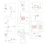
So I pulled out this new revision :

To 'power' amplifier, since I don't have much control on the ground, I choosed a P-Mosfet.
For the power of the computer, I think (still got to test it) I can control it on the low side, so a N-Mosfet will do.
For the motherboard I when for a NPN transistor.
For the power regulation I switch to a 'low dropout' regulator (actually a LM2940C, sorry was not in library), that mean when inactive, with only the microcontroller drawing µA in sleep mode, the regulator will also be drawing very little.
For those who speak electronic (probably better than me), feel free to comment.

