Specs for a tach signal generator

denpo

Carburated Nihilist
Joined
Jul 14, 2010
Messages
2,523
Location
Montreal, QC
In an attempt to troubleshoot my non functioning tach, I'd like to make a tach signal generator.
I'll use a microcontrolleur or a 555-based circuit, depending of complexity of the signal to generate.
Do you guys knows the specs of the signal?
Voltage: 12v,13.8v, other?
Signal shape: square or pulse?
Hz to RPM ration?
Any amp requirement for the signal line?

If anyone has answer to any of those questions, i'm listening.
Thanks.
OK, really OLD geek here, I have a digital audio oscillator, and some left over horizontal output transistors from old color TV sets, from aome 25 years ago.....I have a '75-77 electronic tach in my '72 vette....

the typical tach signal for a stock tach is taken off the sending unit/points? side of the coil, it looks sorta like a sawtooth with a hell of a reverse induction spike when the points are opened there is plenty of power there to fire any tach, and in fact the signal has to be processed through a PI network, the one GM used was two pole.....

That fired my transistor was cap coupled to my oscillator, with an R to ground, the collector went to the 'TACH' side of the coil, along with the tach of course, and that's the same as the collector of the sending unit in the HEI base....I just ran a parallel circuit.....and sat there firing the coil at will, and looking at my Techtronic scope for results....

as you know we run on 60 hz....so at 600 rpm, each cylinger obviously fires 5 times/second......I line lock the scope, and know the pulses are the same when the parade is stable....I went from there, increasing rpm's and counting pulses on the scope time base.....all the way to 6000 supposed RPM's.....

obviously the engine is not running, I"m just calibrating the tach....


:nuts:
 
In an attempt to troubleshoot my non functioning tach, I'd like to make a tach signal generator.
I'll use a microcontrolleur or a 555-based circuit, depending of complexity of the signal to generate.
Do you guys knows the specs of the signal?
Voltage: 12v,13.8v, other?
Signal shape: square or pulse?
Hz to RPM ration?
Any amp requirement for the signal line?

If anyone has answer to any of those questions, i'm listening.
Thanks.
I would speculate that you could get by with a simple 555 based oscillator with a transistor buffer to get a square wave output to the Tach input. The duty cycle shouldn't matter much as the actual dwell signal varies in duty cycle over RPM to allow enough time to charge the coil at all engine speeds. As long as you can supply a square wave output with levels below 2 volts (Low) and 8 volts (High), and a moderately low resistance pull-up resistor (small compared to the input resistance of the Tach filter) then I would guess that this would work as a first try.
Six thousand RPM is ten milliseconds per crankshaft revolution. Half the cylinders fire every revolution, so, there is a firing every 2.5 milliseconds, or 400 Hertz. Ratioing that down, 3000 RPM is 200 Hertz, 600 RPM is 40 Hertz, etc.
This simple circuit/test will just exercise the logic part of the Tach circuit. The input filter portion required to deal with the (real world) flyback voltage will require a fancier signal to debug any issues there.
 
In an attempt to troubleshoot my non functioning tach, I'd like to make a tach signal generator.
I'll use a microcontrolleur or a 555-based circuit, depending of complexity of the signal to generate.
Do you guys knows the specs of the signal?
Voltage: 12v,13.8v, other?
Signal shape: square or pulse?
Hz to RPM ration?
Any amp requirement for the signal line?

If anyone has answer to any of those questions, i'm listening.
Thanks.
I would speculate that you could get by with a simple 555 based oscillator with a transistor buffer to get a square wave output to the Tach input. The duty cycle shouldn't matter much as the actual dwell signal varies in duty cycle over RPM to allow enough time to charge the coil at all engine speeds. As long as you can supply a square wave output with levels below 2 volts (Low) and 8 volts (High), and a moderately low resistance pull-up resistor (small compared to the input resistance of the Tach filter) then I would guess that this would work as a first try.
Six thousand RPM is ten milliseconds per crankshaft revolution. Half the cylinders fire every revolution, so, there is a firing every 2.5 milliseconds, or 400 Hertz. Ratioing that down, 3000 RPM is 200 Hertz, 600 RPM is 40 Hertz, etc.
This simple circuit/test will just exercise the logic part of the Tach circuit. The input filter portion required to deal with the (real world) flyback voltage will require a fancier signal to debug any issues there.
Thanks you so much.
Not sure I got you on the pullup resistor thing, had a quick lookup so far, and seems it's related to a NPN design when you use transistor to 'drain' the current that you otherwise go to the signal input.
If so wouldn't a classical relay(given it can be fast enough) or a PNP transistor design eliminate the need of a pull up resistor?
I'll have a deeper look tomorrow, maybe throw a schematic you could comment.
Thanks again.
 
In an attempt to troubleshoot my non functioning tach, I'd like to make a tach signal generator.
I'll use a microcontrolleur or a 555-based circuit, depending of complexity of the signal to generate.
Do you guys knows the specs of the signal?
Voltage: 12v,13.8v, other?
Signal shape: square or pulse?
Hz to RPM ration?
Any amp requirement for the signal line?

If anyone has answer to any of those questions, i'm listening.
Thanks.
I would speculate that you could get by with a simple 555 based oscillator with a transistor buffer to get a square wave output to the Tach input. The duty cycle shouldn't matter much as the actual dwell signal varies in duty cycle over RPM to allow enough time to charge the coil at all engine speeds. As long as you can supply a square wave output with levels below 2 volts (Low) and 8 volts (High), and a moderately low resistance pull-up resistor (small compared to the input resistance of the Tach filter) then I would guess that this would work as a first try.
Six thousand RPM is ten milliseconds per crankshaft revolution. Half the cylinders fire every revolution, so, there is a firing every 2.5 milliseconds, or 400 Hertz. Ratioing that down, 3000 RPM is 200 Hertz, 600 RPM is 40 Hertz, etc.
This simple circuit/test will just exercise the logic part of the Tach circuit. The input filter portion required to deal with the (real world) flyback voltage will require a fancier signal to debug any issues there.
Thanks you so much.
Not sure I got you on the pullup resistor thing, had a quick lookup so far, and seems it's related to a NPN design when you use transistor to 'drain' the current that you otherwise go to the signal input. You are correct.
If so wouldn't a classical relay(given it can be fast enough) or a PNP transistor design eliminate the need of a pull up resistor? I wouldn't waste time with a relay (slow and noisy). A PNP would work fine, but the nice thing about using an NPN transistor and a pullup resistor is that the resistor is a safety piece (current limiter) in case your Tach input/filter is shorted out.
I'll have a deeper look tomorrow, maybe throw a schematic you could comment.
Thanks again.

Post your schematic when you get the opportunity.
 
In an attempt to troubleshoot my non functioning tach, I'd like to make a tach signal generator.
I'll use a microcontrolleur or a 555-based circuit, depending of complexity of the signal to generate.
Do you guys knows the specs of the signal?
Voltage: 12v,13.8v, other?
Signal shape: square or pulse?
Hz to RPM ration?
Any amp requirement for the signal line?

If anyone has answer to any of those questions, i'm listening.
Thanks.

I would speculate that you could get by with a simple 555 based oscillator with a transistor buffer to get a square wave output to the Tach input. The duty cycle shouldn't matter much as the actual dwell signal varies in duty cycle over RPM to allow enough time to charge the coil at all engine speeds. As long as you can supply a square wave output with levels below 2 volts (Low) and 8 volts (High), and a moderately low resistance pull-up resistor (small compared to the input resistance of the Tach filter) then I would guess that this would work as a first try.
Six thousand RPM is ten milliseconds per crankshaft revolution. Half the cylinders fire every revolution, so, there is a firing every 2.5 milliseconds, or 400 Hertz. Ratioing that down, 3000 RPM is 200 Hertz, 600 RPM is 40 Hertz, etc.
This simple circuit/test will just exercise the logic part of the Tach circuit. The input filter portion required to deal with the (real world) flyback voltage will require a fancier signal to debug any issues there.
Thanks you so much.
Not sure I got you on the pullup resistor thing, had a quick lookup so far, and seems it's related to a NPN design when you use transistor to 'drain' the current that you otherwise go to the signal input. You are correct.
If so wouldn't a classical relay(given it can be fast enough) or a PNP transistor design eliminate the need of a pull up resistor? I wouldn't waste time with a relay (slow and noisy). A PNP would work fine, but the nice thing about using an NPN transistor and a pullup resistor is that the resistor is a safety piece (current limiter) in case your Tach input/filter is shorted out.
I'll have a deeper look tomorrow, maybe throw a schematic you could comment.
Thanks again.

Post your schematic when you get the opportunity.

Make sense now, I get the protection idea.
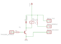
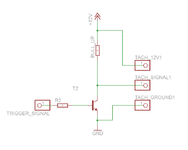
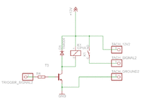
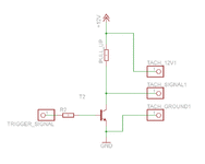
Here's was I had in mind
test2_zps2a07031b.gif
It was purely theoretical since I haven't checked yet relay specs.

But NPN is definitely the wait to go.
test1_zps21581904.gif

So if I follow you I measure the resistance of the signal pin, and put something one order of magnitude smaller for PULL_UP value. Right?

More or less. The input resistance probably won't be easily (accurately) measurable. The pullup resistor just needs to be significantly smaller than whatever the Tach filter input resistance happens to be so that there isn't a significant voltage divider action going on. Just for easy math and explanation, if the Tach filter input resistance was 50kOhm (disregarding the filter caps for the moment), and the pullup resistor was 50kOhm there could be a voltage divider action that would only allow the Tach input to reach 6 volts (half of the 12v battery source) max. If the Tach circuit had switching thresholds of 2v Low and 8v High, the input signal would never get high enough to be recognized by the input circuitry. (I don't have the schematic for your Tach circuit, so I'm just speculating on the switching thresholds.) Just start with a modest resistor (perhaps 1 kOhm) and see where that gets you. (My compliments on the cleanliness of your schematics. :thumbs: )
 
More or less. The input resistance probably won't be easily (accurately) measurable. The pullup resistor just needs to be significantly smaller than whatever the Tach filter input resistance happens to be so that there isn't a significant voltage divider action going on. Just for easy math and explanation, if the Tach filter input resistance was 50kOhm (disregarding the filter caps for the moment), and the pullup resistor was 50kOhm there could be a voltage divider action that would only allow the Tach input to reach 6 volts (half of the 12v battery source) max. If the Tach circuit had switching thresholds of 2v Low and 8v High, the input signal would never get high enough to be recognized by the input circuitry. (I don't have the schematic for your Tach circuit, so I'm just speculating on the switching thresholds.) Just start with a modest resistor (perhaps 1 kOhm) and see where that gets you. (My compliments on the cleanliness of your schematics. :thumbs: )
Thanks.
I'm gonna try this.
Compliments on your awesome didactic effort. :hi:
 
They work :yahoo:
Both the setup and the tach.
Now time to double check the harness before looking suspiciously toward the HEI dizzy.
 
They work :yahoo:
Both the setup and the tach.
Now time to double check the harness before looking suspiciously toward the HEI dizzy.

HEI is easy to check. Hook a 12v testlight to the TACH terminal and a good ground. If the HEI is working, both the pickup coil and the module, the light will blink. Or if the HEI is out of the car on the bench, (be careful- HEI hurts. Don't ask)

Thanks Tim, I will do that if it still don't work.
 
Last edited:
Top