Johnny-bilt hand crank "starter" motor

JPhil

Huh?
Joined
Mar 26, 2008
Messages
1,361
Location
Loveland, Colorado, USA
I need to index my bellhousing for my new TKO600 with the engine in the car. Yeah it would have easier to do when the engine was out but oh well. My SFI rated bellhousing does not have an inspection cover to put a flywheel wrench on. Turning the engine over by the front pulley nut with a socket and big ass breaker bar is a real drag and always makes me nervous.

Gotta be a better way to turn the engine over by hand.

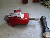
So I went to a starter & alternator rebuilder and got a junk starter motor for free to see if I could make one I can put a wrench on to turn over the engine by hand from below. Here's what I came up with:
66552af3614c550.jpg


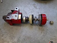
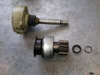
Started by stripping the guts out. I replaced the solenoid throwout & spring with a piece of 5/8" heater hose to keep the gear out permanently.
66552af2662bfb3.jpg


I cut off the commutator & armature by sawing opposite sides to the shaft & splitting it off with hammer & chisel.
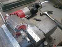
66552af266cac3f.jpg


Fabbed up a planetary gear retainer & and a shaft end support bushing from some polyisocyanurate (?) plastic I had left over from the pressure brake bleeder I made a couple months ago (another fun project that came out well!).
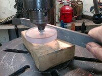
66552af26773912.jpg


Cut a snap ring groove to locate the shaft in place.
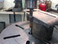
66552af26817101.jpg


Filled the shaft splines with JB Weld (it's very low RPM and very limited use so I figured that will be OK) and filed it down to just under 9/16" diameter, the OD of the splines.
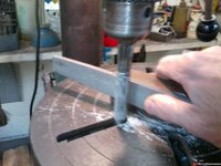
66552af268b261a.jpg


Ground down an old 1" milling machine cutter to fit in my drill press and milled down the motor end cap bushing so the plastic piece would seat against the end of the cap but still have some metal bushing for the shaft. Then I drilled out the plastic support & end cap to 9/16", assembled together for alignment
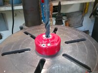
66552af26958ca3.jpg


Cut off the last 5/8" of the shaft which originally was in the end cap bushing. The diameter of the next step of the shaft was perfect to file a square 3/8" socket drive end on it. Cut off the solenoid "tower" and made a little tin cover for the hole. Cut a couple 3" long pieces of 10-32 all thread to make shorter through bolts.

Here's a couple pre-assembly views as it all went together:
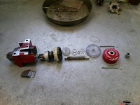
66552c5a9f7e1ce.jpg

66552af58c60af8.jpg


And voila! It's even already painted "Special Tool Red."
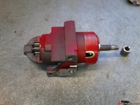
66552c5ad2599e5.jpg

I haven't tried it on the car yet of course, but it spins and with the gear reductions of the planetaries & flywheel, I expect it will hold up & work to slowly turn the engine over.
It took me about 10 hours or so to make-- lots of pondering involved. The only thing I had to buy was a 9/16" drill bit. I'da sworn I had one, but I didn't. Now I do.

Fun project!
 
Last edited:
Most all engine blocks I have seen have two studs to center up the bell housing, and some 6 bolts to hold it on to the block.....automatic trans has the bellhousing cut back at an angle toward the oil pan....

just why do stick shifts have a totally round housing on the bottom, seems it would be good to ensure more clutch air circulation and do them the way auto trans are....for what it worth, for decades now, I leave the lower sheetmetal trans 'cover' off for better cooling, looking at the engine oil pans or any other item in the way, the last thing to get hit would be the TQ or flex plate, for that matter the fly/flex on a stick.....

be ME, just cut the damn housing. and do what I do....stick a pair of vice grips on the flex....and move the damn thing around, obviously easier if you at least loosen the plugs.....:harhar:
 
It's a brand new $600 explosion proof SFI 6.1 competition rated bellhousing, Gene. I got it for a reason. I ain't taking a sawzall to it. And new trannys such as the Tremecs are precision machined with a flange that fits into the precision machined opening in the bellhousing and thus need to be precision aligned to the centerline of the crankshaft of the engine. This ain't junkyard parts swapping.
 
Ya know, the thought crossed my mind, briefly. But then I figured anybody with mechanical knowledge, desire & wherewithall to need something like this could make his own just as well.

It could have been done much quicker and cruder by using a hose clamp & split heater hose for the throwout, a hose clamp & big washer for the planetary retainer, another hose clamp & washer and/or even a little scrap of wood for the rear support, if any. Heck, a scrap of 1/2" heater hose clamped to a socket extension and the shaft would probably turn it.

Or even cruder yet, my very first idea, was to cut off only the commutator, cut down and drill out the end cap, pack the armature housing full of grease and make a tin sleeve hose clamped to the shaft & a socket extension. Use baling wire to hold the throwout fork.

That ain't my style though, when I get to having fun fabricatin'!
 
Last edited:
Ya know, the thought crossed my mind, briefly. But then I figured anybody with mechanical knowledge, desire & wherewithall to need something like this could make his own just as well.

!

it depends on the cost, but, while I certainly have the time and space to build that - I wouldn't if I could buy it and save myself 8 hours of labor... plus, that 9/16 bit isn't cheap
 
Geez, SBG, I have to laugh out loud at that, seeing the things you do! Probably 6 hours of it was settin' and thinkin' and revising and drinking coffee and smoking cigarettes and pondering and revising some more.....One of those projects that started out to just be a quickie cobble job and ended up a deluxe 'work of art'.

And I'm sure I'm the only one here who has ever suffered from 'mission creep'! :amused:
 
Last edited:
mission creep? wouldn't know of it :devil:

I do know, however, the if it were to happen to me that it would come from overpondering :lol:
 
Is there some reason to not just turn it over the traditional way, with a breaker bar on the harmonic balancer?

Just curious, this seems like an elegant solution.
 
Is there some reason to not just turn it over the traditional way, with a breaker bar on the harmonic balancer?

Just curious, this seems like an elegant solution.

I don't have to remove the fan & shroud & loosen the alternator to take the tension off the belt & pulley and then dick with trying to get & keep the socket on the bolt head, I don't have to heave on it and worry about busted knuckles or an over-torqued or busted bolt or busted something else in the engine bay, I can spin it in reverse, I don't have to keep crawling under and back out, I get to use power tools and leverage and finesse instead of brute force, I can be precise in how far I turn the engine, and maybe most importantly I got to make a really cool little tool I'll probably only use once or twice, but I had fun making it and it's really cool!
 
Last edited:
That, is pretty cool. I like it. Something to build when I get some time! There is a local starter rebuilder here who is going out of business because the chain stores with Chinese rebuilt starters and alternators are killing him.
I'll have to see if he has any old chevy starters around.

Nice idea!:thumbs:

Just a few short months ago, we lost an olde tyme starter/alternator place here in Orange Park, but the guy was like my age....71+.....he was a good source for parts....:shocking::goodnight:
 
That, is pretty cool. I like it. Something to build when I get some time! There is a local starter rebuilder here who is going out of business because the chain stores with Chinese rebuilt starters and alternators are killing him.
I'll have to see if he has any old chevy starters around.

Nice idea!:thumbs:


Coming from you, Gary, that is a compliment I can be proud of. Thank you!
 
Part Two: Indicator base

OK so the engine spinner works fine but when I went to put my dial indicator on the crankshaft end I found there was no way the mount I had would work. Hmmm...looks like I get to make another tool! Oh boy, this project is turning into loads of fun!

This one was quick: A trip to Ace Hardware for some metric bits to screw into the magnetic base. A 3" M8 bolt and a bunch of nuts. Of course I bought a bunch of other hardware too, just in case this didn't pan out.

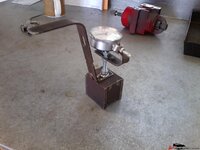
Cut off the head of the bolt. Fold, drill & grind a tang on a piece of flat stock for the gauge holder, double nuts for it all. A hose clamp to hold the indicator works fine.Then I decided it needed a handle to work inside the bellhousing. Drill, cut, bend--voila.

This one only took a couple hours including the trip to the store. Worked fine.

The bellhousing dialed in at .0025", well within the max .005" allowed, so no need for offset dowel pins.

The whole dialing in thing only took maybe 45 minutes at the most. Once I had the indicator in place (& the handle made that so easy), I just sat under the car and squeezed the trigger of the air ratchet, took a reading, repeat as needed. I spun it 360* six times, with a reading at every 90*. Then I decided to double check, so I did it again, another six turns, at 90* but 45* from the first set of readings. All measured out equivalent, .005" total runout equaling .0025" misalignment.

66556fad9fc2432.jpg
 
Last edited:
hello my names is mark and im a/an???

I love it..

guess im not the only one around there are so many custom built tools lying around like a yolk puller for spicer 1350 yokes and a spring compressor Ohlins Monoshocks... oh and a CNC Plasmacutter out of and old computer tape drive robot... and a R8 CNC mill... and we built the DC power supplies for the stepper motors too out of old computer parts... :twitch::twitch:
 
Top