C5 suspension ball joint tapers

daveL82

Well-known member
Joined
Apr 10, 2008
Messages
231
I built my own A-arm rear suspension with my fabricated uprights and stock C3 hub and spindles. I came across a rear C5 suspension complete less diff for $500 so I picked it up.

Been thinking about going with C5 spindles so need ball joint tapers to fab a-arms.
 
The C3 stuff is 1.5 in per ft and the C5 stuff is 2.0 in per ft. Speedway sells the reamers and they should be able to tell you.
 
Last edited:
I'm working the same issue. I have new C6 uprights with the upper ball joints installed -- I'll measure. Coleman Racing Products sells "spindle eyes and tapers" which are weld-on ends for building spindles, but could be used for the upper control arm on a C5 spindle. They list two for a Chevy taper (upper and lower) and one for a Chrysler -- don't know yet if they are correct for the C5/C6 ball joints. They also sell 7 degree (.733 in per foot taper) and 10 degree (1.05 inches per foot taper) reamers. In addition, they have weld-on ball joint sleeves (for the lower control arm) for threaded or press-in ball joints. I am also researching Howe Racing zero-friction ball joints -- they have a new one that screws into the larger Chrysler threaded ball joint sleeve but has "Chevy taper" -- lot's of research yet to do to make the components match up, but I think it is all available. AFCO also has some good stuff. You might also look at the Roadster Shop web-site. They have their own fabricated control arms that fit the Corvette spindle. Hope this helps.
 
Last edited:
I did some looking around yesterday and it appears the C5 uses 7 degree which are 1.5. Will try to post link I found it on later. I've been looking at the Coleman stuff also and used it for my current suspension.
 
I did some looking around yesterday and it appears the C5 uses 7 degree which are 1.5. Will try to post link I found it on later. I've been looking at the Coleman stuff also and used it for my current suspension.

The C5 is definately NOT 1.5 inches per ft. I just measured some C5 ball joints, they are 2 inches per ft.
 
DamnIT! Just this weekend I am set to finish the install of my DIY double-wishbone/unequal/non-parallel A-Arms on the rear. Then on my morning run - was thinking -- wow how much simpler to use C5 bits and...
Nope - that will be my fall back -- But it does have a LOT of merit!

I've got the Passenger side done - so at this point i have a Bicycle - I guess.

Cheers - Jim
 
It's starting to look like both DaveL82 and BBShark are correct. I just took a new C6 upright with upper ball joint installed and inserted the tapered shank into the lower hole in another spindle. The upper and lower tapered shafts are different diameters (lower is larger) and appear to have different tapers. My initial rough measurements show the upper to be near a 2.0 inch per foot taper, while the lower looks like something near 1.5 inch per foot. I have AFX spindles from Speed Tech on the front, and I have several sets of tapered bushings that press into the spindles for various applications. I will check the tapers to see if any match (size is marked on each). My next effort will be to find the correct Moog C6 upper and lower ball joints and see if Howe can correlate those to the correct studs for their low friction ball joints. If I get definitive answers, I will post the results.

Narrowing in on it -- Looks like the Moog part numbers are K6537 lower and K500134 upper. Pfadt sells at least the lower (a rebranded Howe), but it is a press-in fit. I am still pursuing the Howe with the Chrysler screw-in base and the proper (K6537) dimension stud.
 
Last edited:
Howe was able to fix me up with what I needed -- lower ball joints using the correct C6 tapered stud (they mentioned 2 inch per foot taper) and their premium, high strength threaded lower housing. I got weld rings and a dummy ball joint lower housing to screw in while I do the welding to help prevent some of the distortion. I also ordered tapered eyes for the uppers from Coleman -- two sizes listed for upper and lower ball joints. I'll see if either is correct.
 
Dave,

I just got the stuff I ordered from Coleman. The tapered eyes they list for "Chevy upper and lower" will not work for the upper control arm on a C5/C6 spindle. The eye for the upper looks to have the right taper, but it is too large in diameter for the C6 upper ball joint stud. The lower is much larger, probably for the big Impala ball joint. I'll keep looking.
 
I was out of town last weekend so was not able to work on breaking down the C5/6 suspesion assembly. I did manage to get the halfshafts out today and what a pain with it not being in a vehicle. Will try to separate ball joints tomorrow if time allows.

Shame about the tapered eyes. If the taper is correct, may have to drill and use a hand reamer on either new steel or aluminum ones. If I had access to a lathe I might try cutting my own with a flange for use in bolt in type a-arm ends from coleman.
 
IF you buy a bridge reamer that is slightly larger that the
size you need
then get a tool maker to grind it to the angle you need for the ball joint
any good tool maker can do this for you
Just take the ream and ball joint to them and they will work it out for you
BFit
 
Hope you guys have better luck then I did. Bought the Chevy and Chrysler sleeves, slugs or lugs (depending on vendor) and none fit. Ended up buying a 2" per foot reamer and making my own for the UCAs. First try was UBmachine arms, have since changed direction and will fab my own.

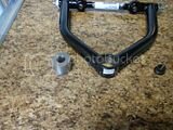
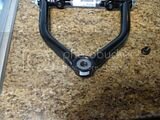
th_C6parts_26.jpg th_C6parts_27.jpg
 
Boredom, Is the plan to weld the slugs into the sleeve provided, apparently for press in ball joints, or will you weld the slugs directly to the tubes when you build your own control arms?
 
Those are the mono ball arms and the plan was to weld the slug into the sleeve. Didn't care much for the cross shaft so I plan on building my own arms now. The slugs will most likely be welded to a plate so the gusset will capture the slug.
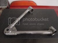
This pic is a good example.

th_fabbeduca2_zps385485e2.jpg
 
Any Updates?

I'm backing up 2 or 3 steps and going down this track now.

I'll be "doing" the weld in Ball Joint Holders, and would like to source teh right parts based on your collective experience. Any part numbers, etc for using the C5 Uprights? Which ball joints have you all settled on?

Pappy - you were working Howes - which ones? How have they worked out?

Boredom - what have you settled on? We have a local machinist that will re-fit/ream my incoming C5 uprights for which ever Ball Joints make sense. Is anybody replacing the bearings with the $KF Racing heavy Duty bearing setups?

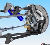
The following is a pic I swiped form somewhere - but represents my basic approach (today - I think :suicide: ). But I'll keep push-rods to the Coil-Overs on top via Rockers.

12695261b67ec07fd.jpg

Cheers - Jim

PS - Pappy - you have a PM -
 
I'm backing up 2 or 3 steps and going down this track now.

I'll be "doing" the weld in Ball Joint Holders, and would like to source teh right parts based on your collective experience. Any part numbers, etc for using the C5 Uprights? Which ball joints have you all settled on?

Pappy - you were working Howes - which ones? How have they worked out?

Boredom - what have you settled on? We have a local machinist that will re-fit/ream my incoming C5 uprights for which ever Ball Joints make sense. Is anybody replacing the bearings with the Racing heavy Duty bearing setups?

The following is a pic I swiped form somewhere - but represents my basic approach (today - I think :suicide: ). But I'll keep push-rods to the Coil-Overs on top via Rockers.

12695261b67ec07fd.jpg

Cheers - Jim

PS - Pappy - you have a PM -

Jim,

Try this thread. It has some good info. http://www.lateral-g.net/forums/showthread.php4?t=42632

Pappy
 
Well, I'm back from South East Asia and working this suspension mod.
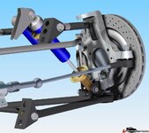
Getting close - but have a question maybe someone can help with. Here are a few pics to make up for the 1000's of words to describe what I need:
first;
1269537c9e55a7065.jpg

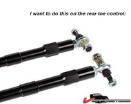
What I'm looking to do;
1269537c9e5658ec5.jpg

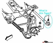
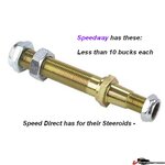
Possible sources;
1269537c9e5603340.jpg

Any ideas on the taper?

TIA - Cheers, Jim

The Speedway details are:
GM:
Stud is 5-1/8" long
Steering arm end has 7/16" thread
Tie rod end has 5/8" thread and is 3" long with 2-5/8" of thread
10 degree taper = 2" per foot
Pinto:
Stud is 4-13/16" long
Steering arm end has 1/2" thread
Tie rod end has 5/8" thread and is 3" long with 2-5/8" of thread
7 degree taper = 1.5" per foot

I'm Hoping the C5 Rear Toe Control is either 7 or 10 degrees taper...
I've seen some reference that the front suspension is @ 6 degree taper
 
Last edited:
Well, thought I'd do a bit of measuring and see what shakes out.
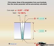
The top (small end) of the location point measures 53/64" on my analog caliper. The large (lower) is 66/64" and over 116/64s and using the calculator I found here: http://www.magafor.com/841/uk.htm

1269537d04f91a86a.jpg

I get pretty close to a 7 degree taper. [6.93 degrees]

Guess I'll be buying the Pinto shafts!

Cheers - Jim
 
Top