You are using an out of date browser. It may not display this or other websites correctly.
You should upgrade or use an alternative browser.
You should upgrade or use an alternative browser.
Aero improvement, or roadhugging weight?
- Thread starter 69427
- Start date
pancake
Well-known member
I don't know the range of pressure you're supposed to measure, but let's take this sensor :
http://www.sparkfun.com/products/9602
Hooking them to an Arduino nano (15$) and hook the nano to a laptop could be pretty easy and cheap to do.
I've been tickling with micro-controllers and sensors, I can help.
You could go with a regular arduino or the mega and record data from multiple sensors.. Here is a sketch someone did like that.. So that way you could put a few sensors on it and get a better picture..
http://forum.sparkfun.com/viewtopic.php?f=8&t=23965
Last edited:
phantomjock
Well-known member
This is tooo Kool
You smart guys need to build us a matrix of sensors - 10x10? We could fasten on a C3 with long enough leads and do some serious data collection! Anyone wants to use the instruments, "buys-in." I'm game - a lot more data than one manometer at a time! Price looks reasonable too.
Any chance the outputs can still jam into excel? That could make some neat pressure diff graphs.
Jim
pancake
Well-known member
Actually, I just had a thought. There are GPS shields for the arduino, too. It's been a while since I looked at them so I can't remember the number of i/o pins and can't remember all the power data.. but I think it would possible to include a GPS shield to log speed data so you could capture the pressure differentials at different speeds to see how everything changes.
denpo
Carburated Nihilist
There is an arduino shield for pretty much anything, accelerometer, GPS, bluetooth, network.Actually, I just had a thought. There are GPS shields for the arduino, too. It's been a while since I looked at them so I can't remember the number of i/o pins and can't remember all the power data.. but I think it would possible to include a GPS shield to log speed data so you could capture the pressure differentials at different speeds to see how everything changes.
I was talking about the Arduino nano because the pressur sensors was using SPI bus, so they could be chained together, 3 required on the microcontrolleur.
There is even a SD card shield, so the controlleur dump the data into a memory card and you analize them later, no need to embark a laptop.
denpo
Carburated Nihilist
I'm asking again :
what is the range of pressure that would need to me measured?
what is the range of pressure that would need to me measured?
69427
The Artist formerly known as Turbo84
- Joined
- Mar 30, 2008
- Messages
- 3,077
- Reaction score
- 38
I'm asking again :
what is the range of pressure that would need to me measured?
My speculation is +/- .5 psi.
denpo
Carburated Nihilist
I'm asking again :
what is the range of pressure that would need to me measured?
My speculation is +/- .5 psi.
That gives us a sensor range of
70-140kPa or
10-20 psi or
0.6-1.3 bar.
I've digged a little deeper :
The cheapest sensor (even if I couldn't find actual price) are the analog ones, that will take a bunch of analog i/o part, arduino mega a least required. They probably need a little bit of calibration.
After that we have the digital one, no calibration, all component on a single bus, simpler architecture.
the sparkfun I've linked is 4-5$ each but they are surface mounted chip, quiet a PITA so solder.
Then we have the digital sensor mounted on it's own board, best
solution, but it's 20$ a sensor at best, that's gonna be a expensive array.
Looks like I'm not the only one playing with microcontroller, this is good, if I say something stupid don't hesistate to correct me.
No ones has connection in the electronic component industry?
By the way, that will take us someone who can print PCBs.
Note: here's some supplier I've found, none of them is giving actual price (I hate that). We'll have to call them for infos :
http://www.meas-spec.com/default.aspx
http://www.allsensors.com
http://www.microfab.de/mems/pressuresensors/pressuresensorevaluation/index.html
pancake
Well-known member
You might check mouser or digikey to see if they have those sensors. I have bought a ton of 940nm IR leds through digikey for an invisible illuminator project I did at work.
I have access to win systems controllers at work but I dont have time to tinker with a project till I get this damned thesis done by Aug 1.
Looks like digikey prices are in the same ballpark was what you found: http://www.digikey.com/product-search/en/sensors-transducers/pressure/1966259?k=pressure sensor
Last edited:
69427
The Artist formerly known as Turbo84
- Joined
- Mar 30, 2008
- Messages
- 3,077
- Reaction score
- 38
I'm asking again :
what is the range of pressure that would need to me measured?
My speculation is +/- .5 psi.
That gives us a sensor range of
70-140kPa or
10-20 psi or
0.6-1.3 bar.
I've digged a little deeper :
The cheapest sensor (even if I couldn't find actual price) are the analog ones, that will take a bunch of analog i/o part, arduino mega a least required. They probably need a little bit of calibration.
After that we have the digital one, no calibration, all component on a single bus, simpler architecture.
the sparkfun I've linked is 4-5$ each but they are surface mounted chip, quiet a PITA so solder.
Then we have the digital sensor mounted on it's own board, best
solution, but it's 20$ a sensor at best, that's gonna be a expensive array.
Looks like I'm not the only one playing with microcontroller, this is good, if I say something stupid don't hesistate to correct me.
No ones has connection in the electronic component industry?
By the way, that will take us someone who can print PCBs.
Note: here's some supplier I've found, none of them is giving actual price (I hate that). We'll have to call them for infos :
http://www.meas-spec.com/default.aspx
http://www.allsensors.com
http://www.microfab.de/mems/pressuresensors/pressuresensorevaluation/index.html
Point five psi.
denpo
Carburated Nihilist
I checked on ebay, the best deal is the BMP805 chip, that comes with a I²C interface.
http://www.ebay.com/itm/1-pcs-BMP08...947?pt=LH_DefaultDomain_0&hash=item27c14d962b
It's actually the sensor you find on most of breakboard.
The only problem is getting them soldered, SMD are such a PITA.
FYI an I²C bus can link up to 112 device over a maximum lenght of 1 meter.
http://www.ebay.com/itm/1-pcs-BMP08...947?pt=LH_DefaultDomain_0&hash=item27c14d962b
It's actually the sensor you find on most of breakboard.
The only problem is getting them soldered, SMD are such a PITA.
FYI an I²C bus can link up to 112 device over a maximum lenght of 1 meter.
denpo
Carburated Nihilist
I'm asking again :
what is the range of pressure that would need to me measured?
My speculation is +/- .5 psi.
That gives us a sensor range of
70-140kPa or
10-20 psi or
0.6-1.3 bar.
Point five psi.
oops, sorry.
It's actually good news, the range is now fully within the affordable sensor range.
69427
The Artist formerly known as Turbo84
- Joined
- Mar 30, 2008
- Messages
- 3,077
- Reaction score
- 38
I'm asking again :
what is the range of pressure that would need to me measured?
My speculation is +/- .5 psi.
That gives us a sensor range of
70-140kPa or
10-20 psi or
0.6-1.3 bar.
Point five psi.
oops, sorry.
It's actually good news, the range is now fully within the affordable sensor range.
As long as the output resolution is there.
turtlevette
The Turdle
I saw that you tested this at Gingerman.
I'm excited to hear your report.
I'm excited to hear your report.
69427
The Artist formerly known as Turbo84
- Joined
- Mar 30, 2008
- Messages
- 3,077
- Reaction score
- 38
I saw that you tested this at Gingerman.
I'm excited to hear your report.
The trip to Gingerman was a last minute thing when a few of my old co-workers in Indiana were talking about going up to Gingerman. I quickly loaded up the car and drove on over. Between family emergencies, last minute meetings, transmission trouble, and no-shows, I was the only one that ended up at the track. Because of the rush I didn't have time here at home to mount and plumb in my differential pressure gauge. It ended up all SOTP feedback.
The setup difference this trip was the belly pan/plates and bigger tires (Nitto 05 275F/285R). The tires allowed a faster corner exit speed, and a lot better terminal speed coming into the next corners. The car felt smooth down the straights, and no brake fade despite the higher speeds. It appears that the air diverters under the front pan directed enough air to the wheel area to keep the rotor/fluid temperatures in line. Also, I had a couple pieces of masking tape hanging inside the hood scoop rear opening to confirm that the pan/plates didn't cause a reduction in airflow to the carb. The airflow there looked normal. The lowered side skirts/rockers survived. I put about a hundred miles on the car and they didn't break.
All in all I was very happy with the car. The next item is to plumb the gauge to the front pan to measure the pressure delta. I'm contemplating end fences on the upper part of the pan if the pressure is higher there than the bottom. Also I might add a soft rubber dam (about 1") under the front edge of the pan to reduce the air flow there in the future. It seems directionally correct, although it will be a bit more PITA loading/unloading the car from the trailer.
Next, it looks like it will be reasonably straightforward to put a bellypan under the drivers side (footwell to pinion bracket crossmember). I'll need to take a wide "notch" out of the trans crossmember (about 1 1/2" x 14") to keep the pan level but I think I can add some internal material to the crossmember to retain its strength. I'd like to do the same to the right side, but the muffler is presently there. Depending on how happy I am with the leftside pan I'll make the decision whether to move the muffler(s) back to the original position to free up the rightside space for the other bellypan. I'm also planning on directing some of the air (that makes it to the pinion bracket crossmember) out to the rear rotors/calipers. This should help brake cooling a touch, and reduce the volume/mass of air that gets trapped in the rear bodywork area.
So, short term I need to drill holes in a few places to put some fittings for the 1/8" plastic hoses that will go to the pressure gauge. The gauge is a 40" of H20 range, which should be sufficient. I hope to have actual measured data at the next track day.
69427
The Artist formerly known as Turbo84
- Joined
- Mar 30, 2008
- Messages
- 3,077
- Reaction score
- 38
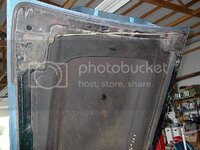
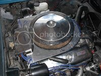
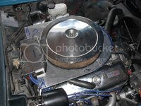
The "damn hot" track day last week got me motivated to finally make an airbox for the carb. I'm always worried about detonation issues, and the underhood air temps being injested by the carb just made things worse. I had some (blue) tape strips hanging in the scoop cowl inlet to make sure the new belly plate didn't mess up the airflow coming into the scoop.

I've got the floor of the box roughed out, and now I'm trying to figure out an easy way to measure the needed side wall height (and contour) so that I can get a decent air seal (to the hood) around the filter housing.

I'm looking to reduce the carb inlet air temp to ambient temperature for better engine protection. Any boost in horsepower is just a side benefit. To be honest, I rarely get outpulled in the straights, but my tire-limited antique does give up something in the corners, hence my efforts to reduce vehicle weight and aero lift.

I've got the floor of the box roughed out, and now I'm trying to figure out an easy way to measure the needed side wall height (and contour) so that I can get a decent air seal (to the hood) around the filter housing.

I'm looking to reduce the carb inlet air temp to ambient temperature for better engine protection. Any boost in horsepower is just a side benefit. To be honest, I rarely get outpulled in the straights, but my tire-limited antique does give up something in the corners, hence my efforts to reduce vehicle weight and aero lift.
damoroso
Well-known member
You know the air cleaner clears, maybe some wadded up tin foil on top of the air cleaner, close the hood, open it, measure the distance from the flat spot on the tin foil to the base you've made. If that works, you could place the foil in different spots to get an idea of what contour you might need.
Use modeling clay with wax paper over the top. Close the hood on the clay/wax paper
69427
The Artist formerly known as Turbo84
- Joined
- Mar 30, 2008
- Messages
- 3,077
- Reaction score
- 38
The "damn hot" track day last week got me motivated to finally make an airbox for the carb. ..............................
I've got the floor of the box roughed out, and now I'm trying to figure out an easy way to measure the needed side wall height (and contour) so that I can get a decent air seal (to the hood) around the filter housing.
I'm looking to reduce the carb inlet air temp to ambient temperature for better engine protection. Any boost in horsepower is just a side benefit. To be honest, I rarely get outpulled in the straights, but my tire-limited antique does give up something in the corners, hence my efforts to reduce vehicle weight and aero lift.
Well, been TIG'ing the side walls on the box. The floor (shown above) is 1/16" (.063"), and I made the walls out of .025" sheet aluminum. I chose the .025" stuff as it's light, but seems to be stiff enough for the job. But damn, is that a PITA to weld! To keep from burning holes in the stuff I have to keep welding an eighth of an inch and then stop, and go to another location. It's taking me forever. After a couple hours of doing this I'm trying to talk myself out of cutting the walls off and making new ones out of .063" stuff. It would be a few ounces heavier but I could at least finish the welding in a half an hour. (And I certainly can't drill any lightening holes in the thing to make up for the heavier material.

