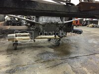
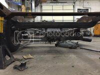
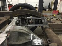
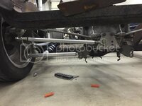
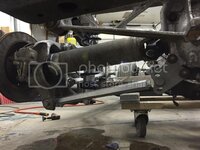
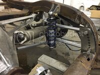
C3/4/5 frankenstein frame

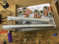
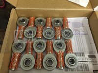
Got my rod ends in today and my hex tube stock should be here tomorrow.
I went with FK bearings RSMX series. .625" hole and 3/4-16 thread with a PTFE liner. They have a 40,000 radial load. Ill be using these on everything except the toe control. The hex tube is 6061 aluminum 1" with a .5" ID. I got 6 feet, which should let me do one side of the car with a bit to spare.
A9628190-BB1B-40E0-9CC6-8310366C31C1_zpshpy9lli1.jpg
 
Small progress today...
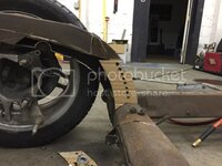
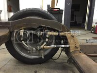
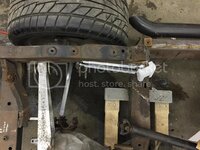
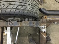
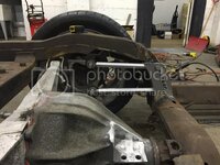
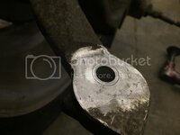
Got the frame rough cut for clearancing the trailing rods. With these on the inside of the entire frame rail (instead of in the rail) Ill be able to box and triangulate it with some tubing (credit to 69427 for the triangulation idea)
C087A4DB-2FF2-4E36-96DD-9BD8F2FBE2B3_zpsrbt87nr6.jpg

BACD671A-7FFF-4643-9FBA-62C954F1BB24_zpshgwzddpe.jpg

Cut some of my hex tubing... Anyone ever bore tubing out on a drill press? Or is this better suited for a lathe?
955C75E0-BE21-43F5-AB7B-723961520157_zpsj5sctsjw.jpg

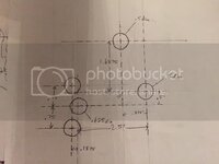
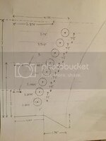
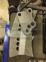
And got these sent off to be laser cut. Please excuse the sloppy drawing :blush:
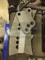
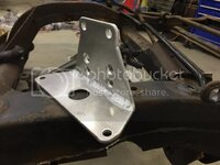
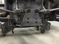
This is the camber rod mount on the diff:
B778FA27-65FD-4F9E-B02F-766AAF077275_zps3mxdnf2g.jpg

And the trailing link brackets:
D70B2FFC-F42A-438B-9B6A-CE2F35523942_zpso3mvmdk8.jpg
 
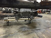
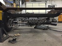
Got my brackets in the mail today :bounce:

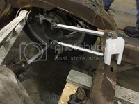
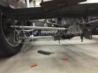
The frame is at ride height +/- .25" in all these pics
0B1373CA-F3F4-442A-9216-726C2268BF6C_zpsqctv4sjl.jpg

510F8327-9F1A-4188-AA61-8CA656D8C44E_zps0l1vrrym.jpg

ACEA2CF7-B3FB-40D4-93BF-357546A34A3E_zpsbqfu9rca.jpg

A little more accurate positioning of the trailing links in relation to the frame rail:
11591ECC-E0F1-49B8-8C87-0F0635A9A53A_zpshgdtzaa4.jpg

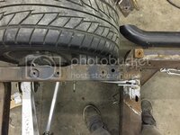
I cut out the entire side of the kickup... Plenty of rust forming between the double wall sections :twitch:
F69B90AC-4312-4C4D-BC28-0BD67B3402DB_zpsbpleglt7.jpg

Not sure how Im going to make the trailing link bolts accessible to change position. As of now, Im thinking of putting an access door in the kickup and pull bolts from that side. I will be putting the triangulation brace back so that makes it difficult to pull the upper bolt all the way out from that end. Other ideas?

Also, the tubing lengths are just estimates until I can finalize everything. then I will account for jam nuts ;)
 
Last edited:
"I will be putting the triangulation brace back so that makes it difficult to pull the upper bolt all the way out from that end. Other ideas?"

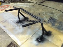
Instead of the triangle braces, maybe a 6 point roll bar.
 
Got my brackets in the mail today :bounce:

The frame is at ride height +/- .25" in all these pics
0B1373CA-F3F4-442A-9216-726C2268BF6C_zpsqctv4sjl.jpg

510F8327-9F1A-4188-AA61-8CA656D8C44E_zps0l1vrrym.jpg

ACEA2CF7-B3FB-40D4-93BF-357546A34A3E_zpsbqfu9rca.jpg

A little more accurate positioning of the trailing links in relation to the frame rail:
11591ECC-E0F1-49B8-8C87-0F0635A9A53A_zpshgdtzaa4.jpg

I cut out the entire side of the kickup... Plenty of rust forming between the double wall sections :twitch:
F69B90AC-4312-4C4D-BC28-0BD67B3402DB_zpsbpleglt7.jpg

Not sure how Im going to make the trailing link bolts accessible to change position. As of now, Im thinking of putting an access door in the kickup and pull bolts from that side. I will be putting the triangulation brace back so that makes it difficult to pull the upper bolt all the way out from that end. Other ideas?

Also, the tubing lengths are just estimates until I can finalize everything. then I will account for jam nuts ;)

Just typing without benefit of looking under my car, but can you drill something like a 1 1/2" hole in the frame upright outward from the upper bolt (and then weld in some tubing to seal and strengthen the hole) so you have a tunnel to install the bolt from the outside?
 
"I will be putting the triangulation brace back so that makes it difficult to pull the upper bolt all the way out from that end. Other ideas?"

Instead of the triangle braces, maybe a 6 point roll bar.

Already done. The stiffer the frame, the better :bounce:

Just typing without benefit of looking under my car, but can you drill something like a 1 1/2" hole in the frame upright outward from the upper bolt (and then weld in some tubing to seal and strengthen the hole) so you have a tunnel to install the bolt from the outside?

Not a bad idea... it would have to be open to access all the holes though.

I have an idea in progress. Going to leave the frame rail solid and weld a piece with threads on the inside of the bracket. Then Im hoping to fab some kind of triangulation piece that will allow me to remove the top bolts via some dimple dies or something similar. Thats the plan at least :hunter:
Lots more stuff in the "idea stage"...
I have a C5 tubular swaybar that I want to try to make work in the rear with some custom adjustable arms, RideTech coilovers are on the way so I can get the upper mount fabbed up, custom toe rod bracket to lower the tie rods so I can move them to the underside of the spindle is also on its way here. Its just too damn cold to get motivated to do anything. :goodnight:
 
"I will be putting the triangulation brace back so that makes it difficult to pull the upper bolt all the way out from that end. Other ideas?"

Instead of the triangle braces, maybe a 6 point roll bar.

Already done. The stiffer the frame, the better :bounce:

Just typing without benefit of looking under my car, but can you drill something like a 1 1/2" hole in the frame upright outward from the upper bolt (and then weld in some tubing to seal and strengthen the hole) so you have a tunnel to install the bolt from the outside?

Not a bad idea... it would have to be open to access all the holes though. ??

I have an idea in progress. Going to leave the frame rail solid and weld a piece with threads on the inside of the bracket. Then Im hoping to fab some kind of triangulation piece that will allow me to remove the top bolts via some dimple dies or something similar. I'm not following your drift here. Thats the plan at least :hunter:
Lots more stuff in the "idea stage"...
I have a C5 tubular swaybar that I want to try to make work in the rear with some custom adjustable arms, RideTech coilovers are on the way so I can get the upper mount fabbed up, custom toe rod bracket to lower the tie rods so I can move them to the underside of the spindle is also on its way here. Its just too damn cold to get motivated to do anything. :goodnight:

I was assuming, due to the brace angle, that only the top one or two locations were too tight to install the bolt from the inside, and that the rest would be accessed from the interior area.
 
"Already done. The stiffer the frame, the better "

A horizontal bar in the main roll bar for seat belts would probably eliminate the need for triangular braces. Or, a second horizontal bar lower tying the kick ups to each other.

Just a thought.
 
I was assuming, due to the brace angle, that only the top one or two locations were too tight to install the bolt from the inside, and that the rest would be accessed from the interior area.

Ill retract my comment "not a bad idea" and say that is a much better idea. I kept thinking that all the bolts had to face the same direction. If my current plan doesnt work out, I think this is the way to go :beer:
 
"Already done. The stiffer the frame, the better "

A horizontal bar in the main roll bar for seat belts would probably eliminate the need for triangular braces. Or, a second horizontal bar lower tying the kick ups to each other.

Just a thought.

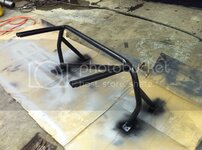
I am potentially losing my previously solid mounted diff as a frame brace (not sure if I will be able to make the aluminum batwing/diff a stressed frame member yet) so Im trying to retain as much rigidity as I can here by keeping some variation of the triangulated brace in place

While not horizontal, the cross bar should achieve a similar result.
D2-A1DFF8B1F312-36303-00001ED10700497C_zpsc52761e1.jpg
 
Last edited:
No huge progress, but I got a few more parts and things worked out...
Got my toe bracket... only to find out that I measured wrong. :cussing: So I will have to have another one made. I think Im going to move the adjustment holes up a bit to level out the rod. Ill punch the numbers into my analyzer and see what that does for me.
BA50CA19-C5DE-483D-AC2B-2AF59E35DC21_zpsbmvbgam7.jpg

E14E325C-28FE-494C-9EF4-42A41CCEE3C4_zpsp2opilkt.jpg

I also cut my hex tubing short... must have had a few too many drinks when I was measuring things that night
456872DA-2BB0-4000-B1A2-97D2BFE9DD27_zpshfddhavi.jpg

Got my tapered bushing fit in to use a .5" bolt so I can mount the toe rod under the arm. (as seen above)
1766B595-B85F-4CE4-9563-832E2751CD1C_zpsp9kxunkb.jpg

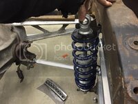
Got my RideTech coilovers delivered... Looks like Im going to have to trim a bit into the storage compartments/rear floor. I may make an access hole there to get to the adjustment knob from in the car. I dont think its going to be too accessible from under the car.
On the floor in this pic you can see my solution for the trailing link bolts... Had a piece of .5" steel cut and tapped then welded to the backside of the bracket.
59417364-551A-4146-9843-B56988946E08_zpskfpimfus.jpg
 
You can mount these shocks upside down
Make it difficult to adjust the ride hight
But that is not a ever weekend thing
Bfit
 
Last edited:
"Already done. The stiffer the frame, the better "

A horizontal bar in the main roll bar for seat belts would probably eliminate the need for triangular braces. Or, a second horizontal bar lower tying the kick ups to each other.

Just a thought.

I am potentially losing my previously solid mounted diff as a frame brace (not sure if I will be able to make the aluminum batwing/diff a stressed frame member yet) so Im trying to retain as much rigidity as I can here by keeping some variation of the triangulated brace in place

While not horizontal, the cross bar should achieve a similar result.
D2-A1DFF8B1F312-36303-00001ED10700497C_zpsc52761e1.jpg

The cage will make it feel like a different car. Even a bad one, as in my case ( first attempt).

You can still add a horizontal bar for belts.
 
Looks like not much is different, but this side of the suspension is almost fully functional! (still need to finish the toe rod) C4 shafts shortened with new spicer joints, shock mounts tacked in, and the frame rail is ready to start piecing back together!

37E8B018-1E14-456B-B964-E3054FDB9CEB_zpsfoaoylbf.jpg

2C536442-6E3F-4A4B-84BD-B93261F459D1_zpsydwrhihb.jpg


Not going to mount the toe rods coincident with the half shafts like Stroker 427s design?

Im ditching the bracket so I can raise the inner pivot up like you said. My plan now is to use the two lower M10 bolts (the ones that bolted my previous bracket to the batwing) and cut the spring perch off so I can use them as my pivot point. They are grade 10.9 so from what Im reading they should have sufficient shear strength to handle the tie rods. I think drilling the rear cover out to fit a .5" bolt would weaken the boss that they thread into too much.
 
Looks good, the C4 rear swap is probably the most cost effective rear upgrade for a C3. How much did you remove from the 1/2 shafts?
 
Top