mrvette
Phantom of the Opera
Here you go Karsten,
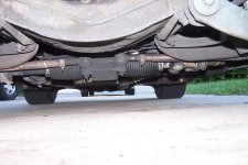
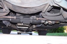
I have a power rack Grand Am, new from junkyard, your rack being manual and shorter? makes it hard for me to comment on how it's rotated, all I can say is that the input coupling was hitting the frame, so I cut a crescent out of it with a hole saw....I have only TWO universals one at the column, one at the rack, and a DD shaft in between, it happens to have a rubber isolator in it, as this all came from various scrap cars...most of the parts are from a Lumina van, as I recall.....:crutches:
I have a power rack Grand Am, new from junkyard, your rack being manual and shorter? makes it hard for me to comment on how it's rotated, all I can say is that the input coupling was hitting the frame, so I cut a crescent out of it with a hole saw....I have only TWO universals one at the column, one at the rack, and a DD shaft in between, it happens to have a rubber isolator in it, as this all came from various scrap cars...most of the parts are from a Lumina van, as I recall.....:crutches: