Suggestions for a cold air intake

this may not be fancy enough but why not use the front part of the 79+ dual air tubing that goes over the radiator and by the front pass side of the car......this will give you the 2 factory engineered feed points and route them into a custom made box around the stacks.

it made my car run tremendously better.

Well, I already have it but I don't see how you can get the filter done with it.

that is the challenge for sure. can you use the existing filters and just build a cold air box around them?
 
Hey, no worries Yves. Sorry this wasn't a workable solution for you. Keep an open mind, you'll find a good solution.

Grampy
 
this may not be fancy enough but why not use the front part of the 79+ dual air tubing that goes over the radiator and by the front pass side of the car......this will give you the 2 factory engineered feed points and route them into a custom made box around the stacks.

it made my car run tremendously better.

Well, I already have it but I don't see how you can get the filter done with it.

that is the challenge for sure. can you use the existing filters and just build a cold air box around them?

The point is that the mesh filters are very restrictive and on top of that they don't filter as well.
 
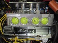
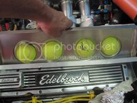
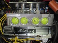
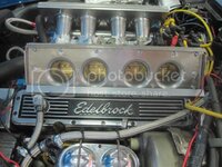
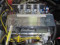
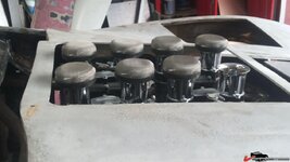
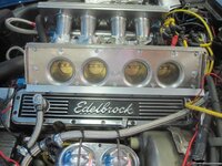
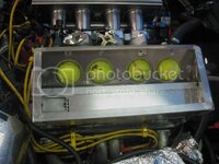
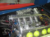
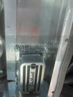
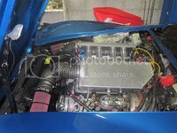
I thought I would throw in some picture of what I'm working on. Not much to see yet, but...

IMG_1193_zps027978f8.jpg
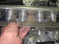
IMG_1194_zpsd3ec455c.jpg
 
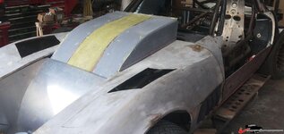
Like that Fit and approach. I was wondering ho to mak a similar cowl induction for my downdraft Webers - maybe I can adapt. Just remove the "horns" - cut a base, reinstall, slip up to the top and - Voila! Instant cowl induction airbox - well nearly. Good idea... Thanks.

Cheers - Jim
 
Like that Fit and approach. I was wondering ho to mak a similar cowl induction for my downdraft Webers - maybe I can adapt. Just remove the "horns" - cut a base, reinstall, slip up to the top and - Voila! Instant cowl induction airbox - well nearly. Good idea... Thanks.

Cheers - Jim

Not quite finished but I will update things here. Had a hell of a time getting the thick plate to fit around the stacks. The consistency on those horns is not what I would have thought; Centerdistances varies some as well. Luckily the box will bolt up to it and I will try using some rubber seal underneath it to seal it against the stacks.

I intend to try and get the airbox to sit above the valve covers. It will looke somewhat like those plastic covers you see on the Corvette LS engines. If it works out well, i might even try putting a carbon layer on top of it for the looks.

The intake tube will be in the front of the airbox. I need someone to fabricate me a cone that will taper towards the rear cylinder so that the air gets evenly distributed over the stacks.
 
Last edited:
Some evolution in my airbox.

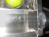
Base plate to keep the box attached sideways on the stack mouths
^
IMG_1193_zps027978f8.jpg

base plate of the airbox attached to the stacks with bolts. To this plate an airbox will be welded that will sit over the valve covers. The next photo shows the approximate angle of what will be the top plate of the box:

IMG_1213_zps162e49a0.jpg
IMG_1195_zpse9e9ea83.jpg

backplate with slots that fits over the stacks. This makes that the rounded edge of the bellmouth gets squeezed between the box base plate and this one.This is the one from the opposite side that is not drilled/tapped for the bolts. It's intended to keep the box from moving back and forth.

IMG_1215_zpsaba4bb9d.jpg
 
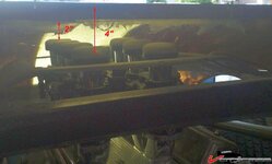
Don't know about your air injection setup - but for my Downdraft Webers, I was advised to maintain at least 2" above the lowest point.

126953ef39eba35f2.jpg
[excuse the hair hanging - still mocking up...]

It is complicated because I am using only cowl induction:
126953ef39ead1c38.jpg

If it was for show only a different solution:
126953ef39eb20840.jpg
I really like your approach and will adapt to my downdrafts:
126953ef3a9ecde02.jpg

Cheers - Jim
 
Not sure how much you need above it, but the mesh filters are very restrictive on that part. Mine made the engine loose about 150 rpm at idle with or without them.

I will have to compromise some. Over here, tech inspection is never going to allow form a hood that obstructs vision to much. Filter sticking through the hood are definatly a no go also.

I bent my plate for the bottom of the box, but had to trim it down because the hood would not close any more. I now have about 7 cm above the outside edge of my valve covers. Way below what I wanted, but it will Always be a compromise and then there is the tubes and filters...
 
Didn't the early crossfire C4's have a duct molded into the hood that sealed against the air box when closed? Would something like that help?

Are your filter(s) inside to box or at he entrance to the duct?
 
I'm going to attach a tube to the box.

At first I was planning on using a filter in the middle that would take air from the cowl, but it has proven to be impossible.
I'm now set on using a cylinderical filter attached to a tube that sits somewere above the A-arms. It's not the best solution but the best what I could do with it.
 
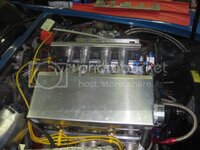
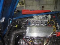
Next phase. The box is almost complete. Top still needs to be made and the tube attached to the front.

IMG_1150_zps421993ec.jpg

I decided I'm going to cover the box in carbon fiber to make it look better.
 
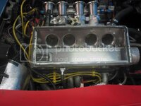
Almost finished item. A little rough around the edges still but this is the general idea.

IMG_1152_zps80367a4e.jpg
IMG_1153_zps30ce37f3.jpg
IMG_1154_zpsd3db26b2.jpg

Had to make some compromised with the intake tube entry. Hopefully it won't disturb things too much.
 
On the other side I'm facing a proble. I cannot put the tube that is higher than the box height sticking out below, since the valve covers are offset from the passenger side and stick out beyond the box. The alternator is also in the way making me move it more toward the centerline. I can have to tube portrude above the box, but then I have a issue on how to make the transition with the box cover and how to seal it. :twitch:
 
update

IMG_1249_zps1c8ce8e6.jpg
IMG_1248_zps0dc00695.jpg
IMG_1252_zps45acba16.jpg

I've used some generic seals that I found in a hardware store (foam type seals that are used to seal of windows/doors). I tested them in an oven during 20 minutes at 100°C and they seemed to hold up fine. Also immersed them in gasoline for an entire night and they were fine. Only the glue dissolved.

I had to disassemble some coolant line for the heater and put in a longer one to clear the right box. Had to refill the coolant system.

Just warmed it up to operating temps to get all air purged out as much as possible and she's cooling down now.

Overall the system seems to work. The sound of the stacks is somewhat reduced although when blipping the throttle there is definatly some aggressiveness in the sound. Odd thing is that the engine seems to want to rock more than I remember. Hopefully this is not because of a difference in filling efficiency due to the box. If that is the case I might have to run a cross over tube of sorts to equalize pressures.
The box seems to stay quite cool during this brief run. Also the stacks themselves stay cooler. I got IAT temps of around 31°C. Outside temps are around 20°C. Not sure if that will remain like this when driving. Looks like it runs about 20°C cooler than before.

Had to put in some rather difficult bends in the right airbox tube to get the filter to sit in the front and to avoid the tube from obstructing closure of the hood.

After warmup I took off the lids and the seals seems to be ok.

Hopefully it stays like that when I'm going to testdrive.

Bit worried if the tech inspectors are going to make a hassle. I might have said this before, but the center between the 2 boxes will be covered with a plate as well. I will graft the top lid of some carb air cleaner on it and call it a cold airbox....Hopefully they will not look any further.

The sound however is a dead give-away if you know what to look for. A million miles away from stock.
 
Last edited:
Yves, in some place inside my PC there is an excel file to calculate the right plenum volume for a single bank of a V8 (alf way between 3 and 4 cylinder engine).

I need displacement,
0.50" intake duration,
Stack ID
Runner length (from the valve to the end)

Is possible to calcolate the volume of the plenum, the ID and the length of the pipe feeding the plenum.

This double resonating system is able to create some RAM effect in two areas:
the resonation of the runners (which is fixed in your case).....
...... but in relaction to your engine configuration is possible to define the right resonation of the plenum/pipe system.

Basically it works like a bass-reflex system for speaker boxes !!!!!!!

Of course the area which is tuneable must be adapted at the fixed area (intake runners ID and legth).

Give me the infos and I will let you know the results.

You don't need to modify the plenum..... may you will need to reduce the volume with some thing inside.

Bye
 
347 ci (4.125"X3.250"X6.250")
247/[email protected]" and .600 lift
Stack id, 50 mm at interface with TB and 85 mm at bellmouth (tapered)
Runnerlength : 12"

After my drive yesterday and based on the VE-table in the EFI system, I've lost around 10-12% in VE in some higher kPa (+80) areas. Only one short run with autotune to rough in the tables. Might get different results when running again. Almost no loss below that kPa zone.
 
You have lost some VE in relation to which configuration ??

And, of course, you was measuring @ WOT, right ??

Which RPM you was when measuring the VE ??

Like any IR induction, the RAM effect of the runners become active only at very high RPM..... in your case very close to 7000 RPM, considering the shape of the mouth.

If you send me the infos..... i will try to help you !
 
Top