12 bolt

rtj

Well-known member
Joined
Nov 5, 2011
Messages
3,153
I’m going to fumble my way though another 12 bolt build, and will update here from time to time. Once, I get some pictures resized, I’ll get some new info up.

So, I’m searching around for info and stumbled onto this
https://www.corvetteforum.com/forums/c3-tech-performance/4296966-12-bolt-failure.html

Ouch!

Tom assembled and tuned my first posi. Also installed the ring gear. I did check the bolt torque. This time, I’ll have to watch his videos on YouTube. I’ve got to figure out how much (or little) the carrier needs to be clearanced, as that was done too by Tom on the previous one.

I was really interested in the Mark Williams stuff until I realized I was way too invested in the 12 bolt stuff to change now.
 
Wow, lot's of drama. Sounds like the guy lost a ton of $

I am unfamiliar with the 12 bolt conversion. What is the advantage? Are the parts still available to do this?
 
Wow, lot's of drama. Sounds like the guy lost a ton of $

I am unfamiliar with the 12 bolt conversion. What is the advantage? Are the parts still available to do this?

Gary is the expert. He is a member here. He has some threads at DC and maybe even here. I think having someone build one is around $5000. Van Steel sells them and some parts (thanks to Ozgreen for reminding me).

Pappy said he has one for sale.

Tom’s still sells the kits, but for how long is anyone’s guess.

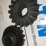
Good news is it looks like all the spider gears are hardened, rumor was Tom ran out, but the ones I got look seriously hardened. I was going to post some photos of what Tom did for me 7 years ago (posi assembly and tuning) and what I have now.
 
Last edited:
I finally burned out on home improvements, trying to get back on the cars.


21945f18e6b54ce8a.jpg

The gears she sent. They look hardened to me. Tom had charged me a very reasonable amount and built and tuned my first posi. Luckily he has two videos on YouTube detailing the steel clutch posi tuning.

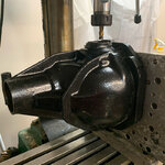
Got a drain plug installed and milled the sides for 1350 inner axles. The big axles only come in a kit from VS, so I got VS 1350 inners. I’ll use them to fill the holes on the spare or gin up adapters.

21945f18e6b5611eb.jpg

The lady at Tom’s said they are out of 30 spline inners, but have 17 spline. I’ve checked all the parts and the kit looks complete, plus lots of extra shims for the steel clutches! I just grabbed the VS 1350’s as they were reasonable and who knows when they are gone too.

Hey, any vettemod layers: is it fair use to upload a pdf that is from a magazine article that is 30 or 40 yrs old? I actually have one with all the dimensions shown from the shop prior to Tom’s.
 
Last edited:
Moving this from the fender flare hack thread.

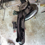
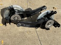
Got the TA pulled, the bushings were kind of bulged, but look okay. They are on the jack stand beside the trailing arm.

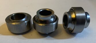
I ordered two qa1 spherical bearings, 1.125 in dia., YPB-8T. ID of TA end is 1.1, but powder coated. They are rated as 25000 lb.

That’s dust on the ta.

21945f287cf1d1e24.jpg

The smallest Johnny joint was 1.5 in ID.
 
Last edited:
I ordered two sizes, same dia, but standard and high misalignment.

21945f2ebfdb2cec7.jpg

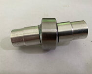
Went with the standard. These are my bushing/adapters.

21945f2ebfdb3d527.jpg

Need to clamp the ta to the mill and take 30 thou off the radius about 1.25 inches down.
 
Last edited:
How will you retain these in the trailing arm?

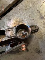
The plan is to use a boring bar to open it up to 1.185. I may or may not put a thin metal sleeve on the inside. That one would be tig welded. The sleeve on the other side would be interference fit with a couple of set screws.

It is 1.1” Id (with powder coat), I don’t know if a 40 thou shoulder is enough. Maybe with tight fit. In not an inside sleeve before boring won’t be too hard.

I’m going to pull the other side before cutting on the TA. The bushings bulged on both side, I guess my contact area was too small.

I really like your solution on the johny joint, but I’m just trying to cut as little as possible.
 
Last edited:
FA4D321F-AA71-42B9-8138-4E52D1EE9D99.jpeg
 

Attachments

  • A82BF27E-4E38-4ACF-8891-881B3840194A.jpeg
    A82BF27E-4E38-4ACF-8891-881B3840194A.jpeg
    298.7 KB · Views: 4
Well, finally got back doing a bit on the cars.
 
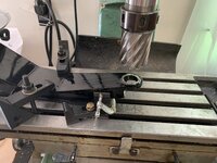
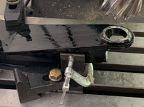
Well, it was a bit “Mickey Mouse” on my part. The arm is heavy duty and the two clamps in the middle were probably enough, but I wanted something quick on the cantilever end.

Luckily the mid section was perpendicular to the end, so fixturing was straight forward.

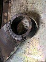
I took your advice BBShark and went for weld on ends.
 
Process. Welds aren’t very appealing, but multiple pass so should be strong.
Welding inside corners was tough, even mini torch was too big. Ended up stick welding and plating over it, so it is boxed now. I struggled to mount the ta assembly on my mill drill, but it looks like if I uses a rotary table they will fit. The TAs need some shock absorber clearancing.
 

Attachments

  • A413F8B3-CE00-4021-8F73-23F33C4D60D2.jpeg
    A413F8B3-CE00-4021-8F73-23F33C4D60D2.jpeg
    325.6 KB · Views: 4
  • B58B120F-844A-423C-AB3D-56604F60E913.jpeg
    B58B120F-844A-423C-AB3D-56604F60E913.jpeg
    358.3 KB · Views: 4
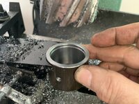
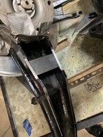
Clearanced both TAs for shocks. I never had a mill when I saw installed originally and just did some file/grinder work. Since this will be slightly less resistant to torsion, I’m boxing them in with a plate.

The duct tape is to keep chips out of the bearings.
 

Attachments

  • 8679F9CA-7B80-4C68-A856-DB88147FED2C.jpeg
    8679F9CA-7B80-4C68-A856-DB88147FED2C.jpeg
    337.3 KB · Views: 9
Clearanced both TAs for shocks. I never had a mill when I saw installed originally and just did some file/grinder work. Since this will be slightly less resistant to torsion, I’m boxing them in with a plate.

The duct tape is to keep chips out of the bearings.

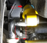
That was my issue also. Made worse because I increased the track width.

1664109335139.png
 
Yes, I remember, at the time I kind of forgot about the fact you had made a lot of mods. You have a good solution.

Since I had already made a mess with the file and grinder, I cleaned it up. :) Luckily I had scored a big rotary table off CL years ago and that gave me the clearance to clamp the entire assembly.

Probably no need to box it, but now was the right time for me, since it was already apart.
 
My plans, get it running again, fresh coat of primer, maybe throw some cheap basset bead locks on it with sticky tires, and maybe try auto cross. Or, most likely, keep doing while-I’m-at-it jobs on it and the camaro. :)
 
full.jpg

If anyone goes this route, deburring the snap rings make things a bit easier.

They mention lining up the hole in the rubber bushing to the grease nipple, but the bushings supplied have none. I plan to carefully drill a hole now they are assembled.

Time to put it back together. The epoxy paint matches the powder coat.

VHT epoxy paint has almost doubled in price since the last time I bought it. It has great shelf life so I haven’t purchased it for awhile. But, at $14 a can, it is a bit pricey. :)
 
Last edited:
This is a pretty old article. But, kind if interesting for the guys that want to stay "old school." :)

I see in a thread over on CF, that Tom's daughter is still working in the business and they are stocking parts like the 1350 axle kit with 30 spline inners (she posted in 2023). Considering how hard these parts are you'd probably save money buying from them rather than machining to dimensions shown in the article.

Not much progress from me, I did buy some of the c-clips from Mark Williams you can machine in a lathe. Yeah, I could have copied them but figured I'd buy them from them.

I did tear down the TA's above and add more 1/8 " steel plates. Figured it was the best time to make them stronger. I'll post some photos. I did tig weld the stand my mill drill sits on and it hasn't fallen down yet in 6 or 8 years and is mostly 1/8 " angle iron, so I may be safe now. :) I'll drop a couple of photos of the extra beefy TA's later.
 

Attachments

Latest posts

Back
Top