clutchdust
Millionaire Playboy
I wrote this up and posted on a local Vette board but figured I would share here also since this is the only true board for the people who actually work on their cars.
Anyway, I apologize it's not more picture intensive. I thought I took a couple more pictures throughout the steps but have yet to figure out what happened to them. In any case, I tried to be as descriptive as possible. Please let me know if this helps you or you find any errors in the article.
Link to article at other board: http://www.sincityvettes.proboards.com/index.cgi?board=tech&action=display&thread=1020
For probably a year or more we have had a problem with the TC/ABS module failing intermittently on the c5. It started out that about every 20 ignition cycles or so it would give us an error on the DIC. By last weekend, the error code was coming on more than it wouldn't, about every 3 out of every 5 cycles.
After reading a couple threads on CF about this problem it seems the most common cause of an intermittent failure of the Traction Control Module is from weak solder joints. All the instructions I have found tell you how to remove the module and send it to someone else to repair. I have some electronics training so I thought I'd take a stab at fixing this myself. Here's the results.
First, pull the module off. Use the instructions from the CF thread if you need specific instructions but the module is located on the driver's side just ahead and below the alternator. It uses six torx bits, don't remember if they're T-15 or T-20 but the one on the top left (looking at the module head on, as in over the right fender) is difficult to get to with a driver, you'll probably need a socket with the bit. Wiggle the module off, you may need to pry it but do so gently as not to damage the weather seal between the module and the hydraulic block.
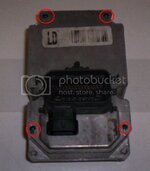
Once you have it out, it should look like this:
At this point, remove the four screws circled in red here. It won't come out just yet as the factory sealed it with silicone. I used a heat gun to soften up the silicone. You will need to pry on the sides but you won't be able to get a prying tool under the top until you get the silicone soft, then insert a sharp blade and gently go around the perimeter cutting the silicone. Take your time and go slow, it will come out eventually.
Once it does, clean out as much of that silicone as you can but be especially careful underneath the coil pack.
The next step will be to break the solder joints that connect the coil pack/circuit board to logic module. For this the best tool is a "solder sucker", if you don't know what that is, you don't have one.
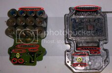
Not to fear though, because you can do it without that tool. Use a conventional soldering iron to melt the solder and use compressed air (a small shop compressor is best but you can get by with those small cans of air used for cleaning computer components) to blow the solder away from the joint. You will need to break the joints circled in red here and also remove the screw from the hole circled in yellow from the block.
Once all the solder joints are clear, gently pry up on the board. It won't come off really easily just because of the silicone so you will need to gradually go around the board as you pry up and cut the silicone to help separate the two. An Xacto knife comes in very handy here.
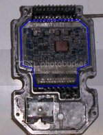
Once separated you will notice the logic module is coated in a non-hardening silicone protectant. Stay the hell away from this! If there is a problem in here, you're pretty much screwed as we're not fixing it. At that point, it's replacement time. The logic module (that's what I'm calling it, don't know what the OEM calls it) is circled in blue. If you're car shows a TCM/ABS error on every key cycle, it's possible this is the problem and what we're doing here won't fix it.
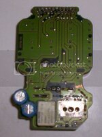
Once you've removed the circuit board, flip it over and put a dab of solder on each joint. An inspection will show experienced electronics people that the manufacturer used the least amount of solder necessary to make these connections. If you're experienced you'll know how little is too little and how much is too much and the range that will provide a good, stable solder joint. The joints are pretty small and I never bothered to inspect them under a magnifying glass to determine which particular joint was the problem. Instead, I just hit all the terminals on this side of the board and put just a little extra solder on the terminals for a stronger joint. After all the joints cooled, I coated them and any parts of the coating that had been chipped with a clear nail polish "borrowed" from the Mrs.
Once that side is done, you're ready to reassemble. Drop the board back over the terminals being sure all the pins go through their respective holes without bending. Resolder all the joints, replace the screw and after the joints cool coat all the joints and screw with the nail polish. The polish will act as a protective coating on the joints and prevent the screw from loosening up.
The final step of reassembly is to take clear silicone and fill in all the accessible voids between the board and the base but avoid the logic module. Place a small bead of silicone around the perimeter of the base and thin to about 1 mil thickness. I then used an anaerobic sealant on the outer flange to seal the two halves together, replaced the four screws and bolted the module back to the hydraulic block.
So far the car has close to 50 ignition cycles with perfectly functioning TCM/ABS and no error codes.
This fix is not for the faint of heart, and is only intended to address an intermittent failure. If yours errors with every cycle (and always has) then it's more likely the logic section has failed and this won't fix it. However, if your module only errors intermittently or at least started that way, this may be all that's needed to return your module to original function.
If you have no experience with soldering, I would stay away from it. But if you know what you're doing, this can be done in a day in your own garage with minimal tools and expense.
If you're experiencing the same intermittent errors, you can remove the module yourself and contact one of the vendors listed on CF or contact me in the services provided section.
Last edited:


