Checking valve to piston clearance

69427

The Artist formerly known as Turbo84
Joined
Mar 30, 2008
Messages
3,023
Location
Clinging to my guns and religion in KCMO.
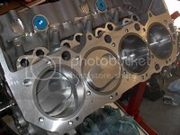
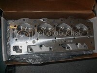
Trying to figure out the next move. I've got the rotating asembly done, and am getting ready to put the heads on. Compared to the engine currently in the car, I've got a touch more dome on these pistons, and the valves are a touch bigger diameter in these heads, so I'm curious about my valve to piston clearance. I'm (eventually) going to use the cam and lifters from the current engine, so right now I don't have anything actuating the valves. I suppose I can put a dial indicator on the valve stem, and then manually compress the valve spring, and then note the distance until the valve stops moving, and then subtract the nominal valve lift to give me the clearance. I would have to do this at piston TDC to get the worst case minimum clearance. If I have adequate clearance at TDC, then I should be fine for when the cam is actuating the valves. If I don't have adequate clearance this way, then I have to figure out if the valve timing particulars allow sufficient clearance. (I've got the cam timing specs filed away somewhere.)That would obviously slow things up. I'm essentially trying to figure out a way to get the clearance numbers without multiple removals and torquings of the head and gasket. These FelPro head gaskets aren't cheap, and I don't know what happens if you "reuse" the gaskets by removing the heads, and then later torquing them down again.

Thoughts, suggestions, opinions?

Thanks,
Mike
 
Put the head on with just a couple of bolts- for measuring, I can't see any need to go thru the whole show. After all it's not going to run anyway. If it hits without a head gasket, IMHO it's too close WITH one too. .045 is still close. Put some light springs on the valves, a wad of clay on the piston at TDC, and open the valve until you feel the clay.

You won't know exactly how much clearance you have without doing all the math (lift, rocker ratio) but you can get an idea.

Thinking about this some more, since you know how much lift you DO have, a dial indicator on the valve and open it that much at TDC.. Pull the head back off and see how deep the depressions in the clay are. Or more exactly, slice thru the clay at the deepest part of the depression and see what's left.

Just my nickel..
 
I agree, take the measurement without a gasket and add the compressed thickness to the measurement you take off your wad of play-doh. No need for a gasket that you won´t be able to reuse.


You could also put some light springs on, put the piston @ TDC and then push the valve down while measuring how deep it goes before it stops on the piston. Add the compressed gasket thickness to it (will have to calculate the height w/ the valve angle in mind and adding the compr. thickness as a component perpendicular to the bore)
 
I remember doing this on my motor. If I remember correctly, the piston chases the valves. So measuring max lift at TDC won't do you any good, since these are interference motors, I think. I could be wrong, I haven't done this in like 5 years and I've done other motors since then.

So to do this correctly you would need to know where on the lobe the lifter would be at TDC... and have fun with that.

Then again, a stock SBC might not have been an interference motor while mine with the high lift cam might be. So who knows. I'm sure TT will set me straight.
 
Last edited:
I remember doing this on my motor. If I remember correctly, the piston chases the valves. So measuring max lift at TDC won't do you any good, since these are interference motors, I think. I could be wrong, I haven't done this in like 5 years and I've done other motors since then.

So to do this correctly you would need to know where on the lobe the lifter would be at TDC... and have fun with that.

True but the valves stays open @ TDC because of overlap and that is the closest it will get- The best way to do it is with the cam in place but that's not an option here.

Knowing how much the valve can go down @ TDC allows you to calculate what you can do as far as cam timing and duration/overlap.
 
If you really have OCD you can put some washers on deck the same (or nearly) thickness as a compressed gasket. Two body washers over each of the dowels should do it. Using body washers because they usually have a nice big hole. The closest point for the exhaust is not usually TDC because on the exhaust stroke the exhaust valve is going down into the cylinder when the piston is coming up. However as TT pointed out if it clears at TDC it will clear anywhere else. But if you are close at TDC run it through a cycle and see exactly how close it gets during it's travel and you may be ok.
 
If you really have OCD you can put some washers on deck the same (or nearly) thickness as a compressed gasket. Two body washers over each of the dowels should do it. Using body washers because they usually have a nice big hole. The closest point for the exhaust is not usually TDC because on the exhaust stroke the exhaust valve is going down into the cylinder when the piston is coming up. However as TT pointed out if it clears at TDC it will clear anywhere else. But if you are close at TDC run it through a cycle and see exactly how close it gets during it's travel and you may be ok.

I can't run it through a cycle very easily. The cam is still in the other engine. That's why I'm currently trying to do it some other way.
 
I've got a clean one I could mail to you. Never been used on a motor, just used it for checking valve to piston clearance. I think it's a .040.
 
Helloooo, just add compressed thickness recalced for valve angle. You know the valve angle right? So you can calc the component perpendicular to the bore, use that and add the comp. thickness and calc back to the full vector length of the valve, now you can calc your clearance. :)
 
No sorry. Sb. You can prob buy a piece of crap one at kragen for 20 bucks like i did.

I think i responded in the title. Im on my phone.
 
Well, I'm quickly coming to the conclusion that my goal of doing a quick and easy measurement of the piston/valve clearance just isn't going to pan out.
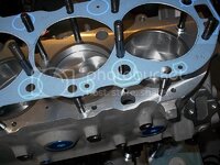
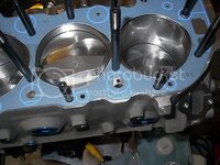
At TDC it just looks like the dome is going to stick too far into the chamber to get by with a simple procedure of just compressing the springs/valves and seeing how far it moves until it hits the piston. The chamber is only 110cc, so it sure doesn't seem to take much dome to get close to a few of the chamber edges.

IM001372.jpg

The outer edge of the intake valve is also stinking close to the head gasket surface (due to the valve angles of a bbc head), making me think that a modest (manual) valve movement at piston (steady) TDC is going to cause contact.

IM001369.jpg

So, it looks like I'm going for the soft spring method (after I locate a couple suitable springs to swap onto the valves), and then transplant the cam and lifters to figure out my "dynamic" clearances. I had to pull the current engine out of the car sooner or later (to use the cam and lifters), but I was hoping for later after I verified there were no "oh crap" technical issues that would cause the car to be down any longer than necessary. The car is presently in one of its rare runnable states. :) I hate to change that.
 
And what keeps you from buying a new identical cam? With all the sweetness in the pics I can't imagine in being the price.
 
You will generally find the exhaust valve is the problem area in valve to piston clearnace because it is opening as the piston is approaching TDC, although high intake valve lifts can also be a problem. Without kowing the cam that is going into the motor, you really cannot properly check clearances. Different durations, advancing-retarding the timing chain sprocket and even the intake/exhaust lobe separation angle will effect valve clearances. You may be able to go to the cam grinders Web site and get a valve lift figure for your cam at TDC to help you check your clearances without the cam being installed. I like the modelling clay method myself but using soft springs and check clearances through a sweep of 20-30 degrees before and after TDC should give you a good idea of where your at for clearance. If not using the head gasket allow for the additional clearances and I wouldn't want a valve to piston clearnace closer than about 0.080"
 
And what keeps you from buying a new identical cam? With all the sweetness in the pics I can't imagine in being the price.

Well, two reasons. This project has gone seriously off budget due to some unforseen issues, so I'm just tired of getting out my credit card. And, the engine (and cam) in the car only has about four or five thousand miles on it. Should still be in good shape, and I don't have to go through the cam break-in process again. If this latest engine works out okay, I was planning on selling the "old" longblock engine, and most guys would want to choose their own cam to suit their purposes anyway.
 
Couldn't you take the valve spring out set the engine to TDC on that cylinder put the cam on the base circle (I'm assuming that all cams have the same base circle dia) and then use an adjustable pushrod to gauge the maximum allowable distance? Then compare that to the cam lift.
 
Head gasket question:

Trying to figure out a head gasket question. A few of the water holes in the gasket are quite different from the block. I understand that some holes in the block need to be large to get the casting sand out, and I'm comfortable with the gasket holes being smaller if they are that configuration to regulate the water flow. However, one of the gasket holes just seems offset compared to the block hole.
First, the top area where there are large passages in the block, and small holes in the gasket, and then the area towards the picture center where the block has a half-moon shape passage.

IM001383.jpg


IM001384.jpg

These gaskets are listed for aluminum heads in the Summit catalog, but there's no reference to block differences, other than bore size. Do all big blocks have the same water passage sizes and shapes, and is that outer odd passage common in all blocks? Or, do I have a parts compatability issue here?

Thanks,
Mike
 
Any chance the gasket is flipped? I think the large water passage is at the front of the block (the part off the right in your photo. The size of the holes may not be a big deal - these are also to help "shake" sand out of the casting when it is made. Look at the holes in the head.
 

Latest posts

Back
Top