guldstrand solid bushings

Belgian1979vette

Well-known member
Joined
Apr 4, 2008
Messages
1,707
Location
Koersel/Belgium
I went to work to do some mods to my suspension before starting final assembly on my car.
I was going to mount the guldstrand solid bushings for the uppers A-arms. These have out of center holes in them and I do not remember how these should be mounted. I seem to have lost the instructions.

Should they be able to rotate or not ? On Guldstrands site they mention that you could dial in you suspension with them, but then they would need to be loose, which seems rather strange.

Can anyone help me with this ?

Thanks

Yves
 
i'll copy and paste this i just responded over on CF.

If you want to increase negative camber, you need to mount the hole offset away from the center of the car. In addition, it helps geometry to lower the mounting point.

My instructions said to install the left(driver) side at the 10 O'clock position(moves the arm down and towards the center line of the car) and the right(passenger) side at the 2 O'clock position (again moves the arm down and towards the center line of the car)

These are not intended for a car that is driven a lot. Mine wore out in about a year causing the car to fail inspection. You have metal on metal contact and the soft material will wear quickly. Marck did warn me this was going to happen. You need to keep fresh grease in them at all times.

They are ribbed where they press into the trailing arm to prevent them from turning, but it's best to tack weld them in to be sure. If they turn, your camber changes drastically.
 
Last edited:
Fyi

OK, I just wanted to let you guys know.

I have the original solid bushings of Guldstrand, but I'm using the VBP upper A-arm with the extra caster built in to them. The guldstrands don't fit these, so i had special solids turned for the exact diameter of the VBP's.

I tried to assemble them today, but stumbled onto a problem which i think is the reason why rodeck's wear out so fast. I noticed that they eyes on the trailing arms don't align exactly and for solids with only minimal clearance, this doesn't work. I couldn't get the bushings all the way or the shaft would get freezed up.

I assume that with an OEM A-arm these flex more than the VBP piece, so that makes it probably possible to get them in all the way, but any minimal alignment error in the eyes of the A-arm will cause the shaft to bind or press more on one side of the bushing causing it to wear out prematurely.

I'm going to take of the eyes of the VBP's, put the bushings on and reweld them to they A-arm tomorrow.
 
Last edited:
Yes, you will need a different shaft in order to be able to slide it inside (a long portion of the same OD in one side...), but this should be te "final solution".

Of course even the A-Arm need to be modified with a threaded portion of tube.

A more difficult job...... but that will something unic in your car! ;-)
 
I know Pier Paolo, but the arms i've seen are pretty much different. You need a threaded tube and this needs to turn. So that makes it difficult among other to retain the bumper which now sits underneath the A-arm.

Plus I already have the hardware and invested the money.

This is a small setback. I would have assumed that the quality on these VBP would have been good,but now i find out that the eyes are not aligned and i need to cut them loose. Otherwise I would already have been ready.
 
Just an update.

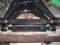
Here is a picture with the 2 arms lying on top of eachother. Notice that the eyes are sitting closer together on the lower arm (right side). This was the one i was working on. The eyes were sitting so close together that the shaft could not be taken out when i started with this. Could be that the pressing of my solid bushings caused the eye to bent a little more, but nonetheless something was amiss with these arms

1194d037334649f9.jpg

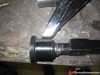
Here is a picture with the poly bushing on both sides in the eye. Notice how much further the eye moves from the rod of the A-arm. The eye on the other side is still attached in this stage. Both sides turn freely now.

1194d0373352795a.jpg

I think my right arm is better, but when putting a straight beam across them, they still point inward a little although not as bad as the left one
 
Last edited:
Yes, I agree with you!

Sincerely I'm not surprised of the tolerances of the arms..... even if they welded everything in a jig, as you know, cooling down the arm will deflect.

Have a fun with your new A-Arms....... something "done by hand" in the car, for my opinion, is a great satisfaction!!!!!!!!!!!!!!

True, the thing is that with rubber bushings as per stock it won't matter. The rubber will take up any alignment error. However with solids or with poly's this is not so much the case. I think a lot of the squeeking with poly's will happen because of this reason.
 
Course they doing production shit, so they takes their chances on those weld/warping, I suppose....

My welder buddy is super critical about cooling down stuff after it's over....

hold it in the jig until cool enough to touch....I always thought it a waste of time, guess he right afterall, never discussed my opinion with him because he doing it for FREE, so can't bitch, and stand clear....

:bonkers::hissyfit::waxer:

If it's something that needs to be exact in dimensions, i would say he's absolutely right.
 
Well, i also trial fitted the solids on the lower arms. The bushings were not sliding over the shaft easily, so i went to a friend with a lathe and used some sandpaper while the shaft was in the lathe to size it down a bit.

Oh boy, the shaft started wobbling around. On sight it would appear straight but not so...Anyway i got the bushings on alright but of course when trying them in the arm, the shaft started freezing up.

Does anyone have any idea if new shafts are true ?
 
Last edited:
Well, I finally got the upper in the eyes and when you can the excenter hole aligned properly at least, these seem to be able to turn freely.

The lowers are becoming a serious hassle as nobody seems to know for sure that the shaft that they sell are completly straight. Most say they are never straight, even when NOS new...
This would mean that the lower will never work properly.

And then there is also the fact that I can't seem to get a fair answer on the wear aspect. Some say that they wear out, but nobody ever seemed to have aligned the bushings properly.

I certainly do not want to keep the poly's in there because after what I've seen the for certain have to much play and secondly they will probably squeek big time.

I'm almost going back to the stock arms and rubber bushings, and say to hell with it.
 
It's hard to imagine the shafts aren't turned straight when new, even though they did a very rough cut job of it.

If you have access to a lathe, and were originally considering solids, then Delrin is another alternative, very easy to machine.
You could then probably straighten your lower shafts with a minimum cut and even make, weld and line ream new bushing mounts after welding.
 
I know about the delrins. Global west sells these, but their system is with a threaded shaft that needs to be welded to the original shaft. Doesn't look an easy thing to do. Anyway i'm talking to a guy that has the delrins. I'll see what he has to say about them. I know he uses MOOG shafts and these seem pretty ok.

I drew up a design of the lower shafts in Inventor and i sent that over to my machinist for CNC'ing them. I'll see what the price will be for a pair. I put a threaded shaft on the ends so that i can use a castle nut with them and secure the bolt against loosening up.
 
Coming back to this.

I have made a cad drawing of a set of shafts that should come out straight on a CNC. It was very difficult in finding someone that could make me an offer on a set, but today i got a price ....€ 1250 a piece....WOW....:bullshit:
 
Coming back to this.

I have made a cad drawing of a set of shafts that should come out straight on a CNC. It was very difficult in finding someone that could make me an offer on a set, but today i got a price ....€ 1250 a piece....WOW....:bullshit:

how many did you order:)

2 pieces of course, nevertheless...
 

Latest posts

Back
Top