JeffP1167
Well-known member
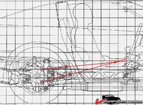
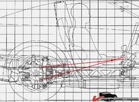
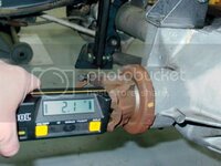
As part of my c4 suspension into c3 frame swap the rear suspension will enter the picture. Is correct placement of the batwing mounts determined by pinion angle? What determines how high or low to mount the batwing? In a installation article I read 2-3 degrees is a preferred setting.
I assume the placement of the control arms on my c3 frame would be more in the area of the stock c3 trailing arms. What determine the angle of mounting the control arm bracket?
I will be using the factory rear transverse spring so by using all the stock stuff does this eliminate some of the guess work on fore and aft position of the control arm bracket or is wheel base the deciding factor?
After the front suspension is grafted into place and the frame is still on a jig is it best to mount the motor and transmission to set the rear end up & when you get the 2-3 degrees of pinion angle how do you determine the best angle for the transmission mount?
I believe the 82 has a steel driveshaft (but not sure) but either way will the C4 driveshaft from the c4 be the better choice due to possible u-joint differences?
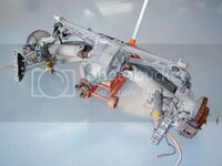
Also what are the square looking blocks by the batwing mounting bushing?
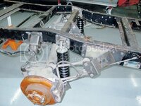


Last edited:

