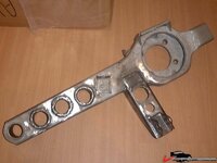
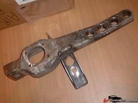
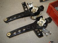
Here's the deal on the 6 link. I suggest you read this first:
Tech Aticle: Roll Axis, Roll Center and Instantaneous Center
Now for a little more info. I used FlexusMark's pics.
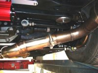
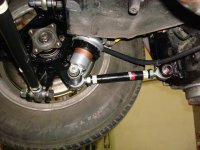
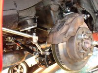
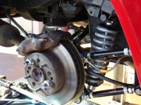
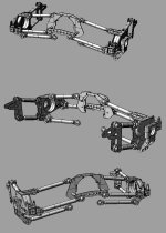
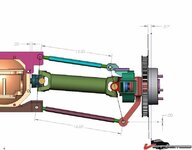
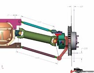
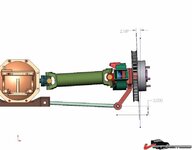
The following 3 pics are how you HAVE to do it if you want to stick with the stock fixed shafts and c clip in place. It's still recommended to remove the clip because you will only have the available play in your stub axle for tolerance and adjustability when adjusting the upper and lower strut rod. If you have to make significant camber adjustments this will lead to having to adjust each one a little at a time, alternating between the 2 to keep them from binding. It also means that you can't adjust the camber way off because of geometry constraints. It's therefore not recommended to keep the C clip. Without the c clip you can adjust the 2 rods to pull the stub out just a little. Sticking to this shared instantaneous center method will result in the least possible stuck axle movement. Because of tolerances and adjustments there will be some movement, ideally when strictly adhering to this setup there should be none but that's only in the ideal situation. Finding actual IC is problematic. It can be done roughly by stringing, then fabricating the mount and tacking in place (with no shock or spring load) and carefully adjusting for bind and stub axle movement.
Shared instantaneous center between lower rod, halfshaft and upper rod, shared pivot planes.
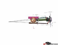
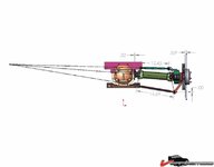
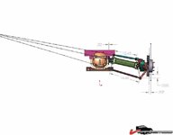
With this setup the camber curve will remain what is dictated by the lower strut and halfshaft. Even if the halfshaft is no longer a controlling member with the floating stub axle, it does determine the IC and therefore the geometry (and camber curve) When repositioning the lower strut (inner mounting point), this also translates into a new position for the upper one.
NOTE that apart from the instantaneous center, the 3 inner picots (and the 3 outer ones also) are IN THE SAME PLANE! Note the line though the rod ends and u joints. This is a requirement to get a perfect trapezoid.
In the 3 pics you can see that stub axle movement is at a minimum, with a .32" distance between stub and case.
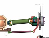
Next we have a setup where the camber bracket has lowered pivot points. This results in a parallel lower strut rod and halfshaft. A situation commonly used with "smart struts". This will result in a reduced camber curve.
An upper rod was also installed and the pivot point planes are shared amongst the 3 members. The 3 members do NOT share an instantaneous center and stub axle travel is increased. However, the camber curve is no longer the same as that set by the lower rod and halfshaft. This way you can create a curve that may suit your requirement. However the halfshaft and stub play are still limiting your setup, this is where the telescopic shaft comes in, they greatly enhance your possibilities. Not only for this setup below but for all the following ones and this will make it clear why it's easier to fabricate a 6 link that way because you won't have to strictly adhere to the IC & geometry set by the fixed halfshaft.
Shared pivot planes, non shared IC, parallel lower rod & halfshaft
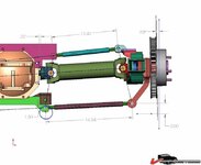
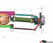
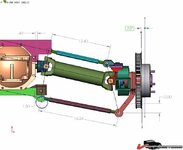
The same idea but the inner pivots are not in the same plane:
NON shared pivot planes, non shared IC, parallel lower rod & halfshaft
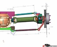
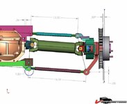
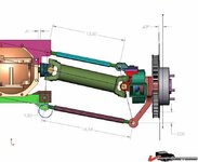
Yet another setup this time the upper rod is parallel to the halfshaft
Non shared pivot planes, non shared IC, parallel upper rod & halfshaft
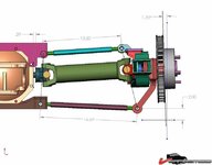
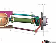
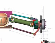
And nothing parallel.
Non shared pivot planes, non shared IC, no parallel rods & halfshaft
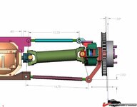
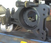
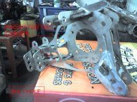
The situation where the outer pivots are not shared is not being discussed but it too will contribute to travel play and the resulting camber curve. The outer pivots are easy to plot with a completely assembled trailing arm assembly on the bench. The HEIGHT of the outer pivot is to be chosen wisely. The location means that it's right where your bumpstop is, so don't make it too high. Too low and you have to mount the inner pivot even lower, possibly too low to clear the spinning stub axle. A good idea is to mount it high enough to not interfere with the frame and/or the bump stop. Especially if you use a cut down bumpstop. Only after the outer upper position is determined can you select the inner one.
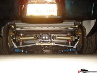
Most systems I've seen being fabricated have not been using the 1st method of shared IC & pivot planes. Instead a stud has been welded to the crossmember and a rod end attached. The resulting stub axle movement will be whatever it comes out to be although it can be reduced by reducing suspension travel.
I would rather keep my stub axle fixed, side movement must certainly contribute to wear, possible oil wicking out and wear of the seals. The splines will most likely wear out faster too. IMO the sliding shafts are the best way to go about fabricating/building your 6 link setup.
Stock setup
 Smart strut type setup with lower inner pivot & reduced camber curve
A little bit about the smart struts. On other forums it's commonly said that parallel lower strut rods and halfshafts give you 0 camber gain! This is obviously false. It WOULD be true if the members would form a parallelogram, however they do not, they form a trapezoid and because of the angled sides they will give you camber gain because the effective perpendicular component changes between the 2 as the other 2 members (halfshaft and strut rod) angle away from horizontal. It's analogous to how a steering box steering system works, the center link is connected with the pitman and idler arm. These 2 are angled towards the rear diff, forming a trapezoid and thus alowing for different steering angles on the in and outboard wheel. This is known as ackerman.

