You are using an out of date browser. It may not display this or other websites correctly.
You should upgrade or use an alternative browser.
You should upgrade or use an alternative browser.
1969 427 restoration from Sweden
- Thread starter 427Swede
- Start date
427Swede
Well-known member
427Swede
Well-known member
427Swede
Well-known member
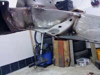
As usual the underside of the front cross member was buckled and destroyed.
removed the bad parts and welded a 6mm plate (1/4" approx.) at the bottom.
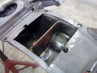
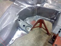
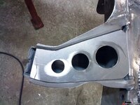
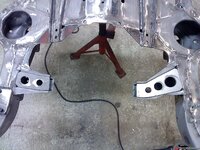
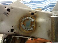
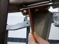
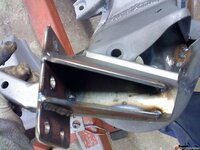
Then 3 plates with a 6mm thickness was welded to the crossmember. Perhaps it can be seen on the picture that I drilled holes in the middle plate so that the inner plate could be welded to the outer through the holes (filled with weld on the photo)
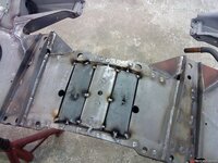
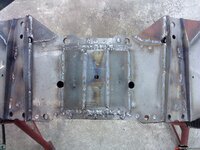
I also welded plates at 90° angle on the two side plates on the inside to give them some bending strength. Also completetly welded the connections for the lower arms as seen in the photo
removed the bad parts and welded a 6mm plate (1/4" approx.) at the bottom.

Then 3 plates with a 6mm thickness was welded to the crossmember. Perhaps it can be seen on the picture that I drilled holes in the middle plate so that the inner plate could be welded to the outer through the holes (filled with weld on the photo)

I also welded plates at 90° angle on the two side plates on the inside to give them some bending strength. Also completetly welded the connections for the lower arms as seen in the photo

Sharkey1807
Well-known member
A long time ago i learned each kind of different welding technics at then still existing Swissair.
I feel a bit sorry for your frame. Whit all that heat applyed it's almost sure you will need a good alignement shop.
Just holding it together with those beams wont do the job and prefent from twisting. Maybe as long as the frame is fixed to them it will, but after removing them ??
I don't want at all to discurage you. But i really would be concerned about the straightness. Wish for you all is going well and not too much twisting after removing the beams.
Otherwise cool seeing or project going on.
Greetings
Robert
427Swede
Well-known member
Hello Robert,
Thanks for your input. As I said earlier in the thread, I measured the frame before welding, according to the C3 dimension drawing.
After welding and removing it from the jig, I measured all dimensions again and compared it with the old measurement. I did not find any deviations during this comparison that was larger than 2mm. Proof enough.
I am well aware of how steel behaves when heat is applied to it and how to weld to avoid distortion of steel sections. Actually, it is part of my daily work since 15 years and I would not have started this project if I did not think I could handle it. Do not feel sorry for my frame, it is in better condition than many frames out there...
Regards, Daniel
427Swede
Well-known member
Ok, lets continue this thread with some more welding:bounce:
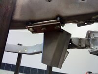
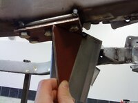
Decided to incorporate a support between the front spring towers. Manufactured a connection that is removable.
It is bolted with two M10 screws (approx 7/16" Ø). I know it sits a bit lower than the supports you can buy but I think the solution when it is bolted to the upper control arm looks a bit flimsy. I may be wrong, but that´s ok.
It will not have the same leverage as the upper alternative, but it will be better than nothing at least.
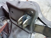
Test fit at right side.
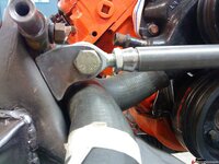
Finished installation.
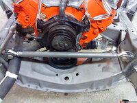
Decided to incorporate a support between the front spring towers. Manufactured a connection that is removable.
It is bolted with two M10 screws (approx 7/16" Ø). I know it sits a bit lower than the supports you can buy but I think the solution when it is bolted to the upper control arm looks a bit flimsy. I may be wrong, but that´s ok.
It will not have the same leverage as the upper alternative, but it will be better than nothing at least.

Test fit at right side.

Finished installation.

427Swede
Well-known member
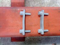
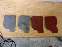
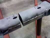
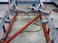
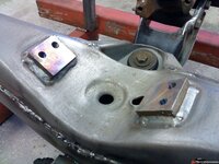
Continued then to manufacture a removable cross member. Cut some adaptor plates. Machined them round and smooth and cut the cross member at one side to give room for the plates.
Assembled the plates in the correct position and fixed them with a few small weld spots. Continued the same way at the other side. Welded everything completely thereafter, taking care to avoid heat build up and changing from left to right continously, no problems with warping.
If you look closely, there is a shim between the plates made from brass to avoid having the parts getting jambed if, the member would warp. The brass shim allows easier removal after welding. After powder coating all parts I cut stainless shims with different thickness so that the cross member could be shimmed to a very tight fit.
Plates
Cutting
Spot welding of plates in position.
Everything in place
Ready!
Assembled the plates in the correct position and fixed them with a few small weld spots. Continued the same way at the other side. Welded everything completely thereafter, taking care to avoid heat build up and changing from left to right continously, no problems with warping.
If you look closely, there is a shim between the plates made from brass to avoid having the parts getting jambed if, the member would warp. The brass shim allows easier removal after welding. After powder coating all parts I cut stainless shims with different thickness so that the cross member could be shimmed to a very tight fit.
Plates

Cutting

Spot welding of plates in position.

Everything in place

Ready!

427Swede
Well-known member
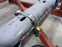
Decided to do something about the cardanshaft when I realised that it was only a few inches from my kidneys/back when sitting in the car and only a thin sheet of plastic is protecting me:twitch:
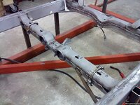
Machined two steel plates with threads and welded them to the frame in the rear. I also added connection points to the removable cross member so that a front safety loop can be added.
This work was all done AFTER the complete driveline and engine were modified for correct drive line angles so that the position of the cardan shaft was the final and correct one. As seen on the photo, the loop is not finished completely. (have to remove excess material at each end)
Rear safety loop connections.
Safety loop
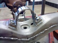
Cardan shaft and loop. The distance around the shaft to the loop is 8mm (5/16"). It should be enough to allow movement of the driveline during driving. If not, I will make a new loop.
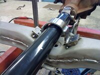
Machined two steel plates with threads and welded them to the frame in the rear. I also added connection points to the removable cross member so that a front safety loop can be added.
This work was all done AFTER the complete driveline and engine were modified for correct drive line angles so that the position of the cardan shaft was the final and correct one. As seen on the photo, the loop is not finished completely. (have to remove excess material at each end)
Rear safety loop connections.

Safety loop

Cardan shaft and loop. The distance around the shaft to the loop is 8mm (5/16"). It should be enough to allow movement of the driveline during driving. If not, I will make a new loop.

Last edited:
Kid Vette
Master-Baiter
Very impressive!! Keep the pics coming! :thumbs:
427Swede
Well-known member
I´ll keep the photos coming, thank´s for the encouragement Kid Vette
So, after reading a lot of posts at different forums I thought it would be a good idea to buy a rack and pinion steering system. The old system was leaking badly but it actually wasn´t too sloppy. I was a bit surprised during my first drive ever in a Corvette that the steering had such a nice and precise feeling after +40 years.
Bought a rack and pinion system from a well known company (I´ll leave the companys out) and the first surprise came when I opened the box. The tie rods were in bare aluminum and machined at each end. Not at all the appeareance shown in adds on the net:crap: Sent an email with a question regarding this and quickly got an answer that they had two suppliers for that part. Acceptable explanation, I´m fine with that. Good to get a quick respons anyway.
Next surprise was the finish of the rack unit. Painted with a silver spray over the old paint which had not been removed:crap: Also something I can fix but irritating.
The third surprise was the orientation of the oil tubes on the rack. Probably what the rack was equipped with from the beginning. I would have expected at least new lines orientated correctly with a minimum quantity of bends. I even had to rebend the tubes to get them away from the oil pan:crap:
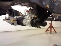
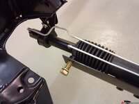
Started to test assemble the welded brackets on the frame and the left side did not fit. As seen on the photo the angle between the main plate and the support plate is incorrect. Not possible to assemble.:crap:
Tested the right side and it did fit correctly. Then I tried to pull at the lower end of the bracket where the rack assembles and the bracket moved considerably even with a light pull:crap: No way I would get on to the high way with that connection.
So, what to do about this? I cut the left side connection apart and rewelded it to one single unit modified to fit the original connections. Nothing complicated.
The right side was a bit more complicated. I machined a thick steel plate and made 4 threaded holes in it. Welded it to the underside of the frame (well, it took me a few hours to get it correct) and modified the bracket with support plates so it could be bólted to the frame as one unit. Now free from flex and securely bolted to the frame.
I have no doubt that the rack system would have worked right out of the box (with som tweaking), but I really do expect more when I buy expensive parts like this. I also do understand that Corvettes are not all the same so it is probably difficult to manufacture a system that fits perfectly on all cars.
The non fitting left side bracket
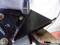
Modified left side bracket
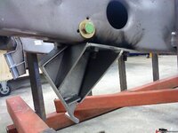
So, after reading a lot of posts at different forums I thought it would be a good idea to buy a rack and pinion steering system. The old system was leaking badly but it actually wasn´t too sloppy. I was a bit surprised during my first drive ever in a Corvette that the steering had such a nice and precise feeling after +40 years.
Bought a rack and pinion system from a well known company (I´ll leave the companys out) and the first surprise came when I opened the box. The tie rods were in bare aluminum and machined at each end. Not at all the appeareance shown in adds on the net:crap: Sent an email with a question regarding this and quickly got an answer that they had two suppliers for that part. Acceptable explanation, I´m fine with that. Good to get a quick respons anyway.
Next surprise was the finish of the rack unit. Painted with a silver spray over the old paint which had not been removed:crap: Also something I can fix but irritating.
The third surprise was the orientation of the oil tubes on the rack. Probably what the rack was equipped with from the beginning. I would have expected at least new lines orientated correctly with a minimum quantity of bends. I even had to rebend the tubes to get them away from the oil pan:crap:
Started to test assemble the welded brackets on the frame and the left side did not fit. As seen on the photo the angle between the main plate and the support plate is incorrect. Not possible to assemble.:crap:
Tested the right side and it did fit correctly. Then I tried to pull at the lower end of the bracket where the rack assembles and the bracket moved considerably even with a light pull:crap: No way I would get on to the high way with that connection.
So, what to do about this? I cut the left side connection apart and rewelded it to one single unit modified to fit the original connections. Nothing complicated.
The right side was a bit more complicated. I machined a thick steel plate and made 4 threaded holes in it. Welded it to the underside of the frame (well, it took me a few hours to get it correct) and modified the bracket with support plates so it could be bólted to the frame as one unit. Now free from flex and securely bolted to the frame.
I have no doubt that the rack system would have worked right out of the box (with som tweaking), but I really do expect more when I buy expensive parts like this. I also do understand that Corvettes are not all the same so it is probably difficult to manufacture a system that fits perfectly on all cars.
The non fitting left side bracket

Modified left side bracket

Last edited:
427Swede
Well-known member
427Swede
Well-known member
denpo
Carburated Nihilist
Keep the engineering porn coming :clap::nuts::thumbs:
MYBAD79
Moderator
awesome job, that reminds me that I have a steering rack waiting in my garage.... time to rip the stock steering out of my '79
keep the updates and pics coming
keep the updates and pics coming
Sharkey1807
Well-known member
Cool idea with your shaft safety.
And the new steering system looks killer.
Great work.
Robert
And the new steering system looks killer.
Great work.
Robert
427Swede
Well-known member
Again, thank´s everyone for your kind word´s.
I do not write anything in other threads yet myself, but I do read many of them with great interest. When I think I can contribute with something in a thread I will do so. A lot of cool builds and lot´s of knowledge gathered in one place! Respect from me to all of you:thumbs:
Well, the next step for me in my build was to do a test assembly of the complete driveline to make sure everything fit properly. At this stage I had already been reading articles about drive line alignment, also here on Vettemod where I found an excellent post regarding the subject by Twin Turbo. I also checked out the theories on this at the web pages belonging to cardan shaft manufacturers here in Europe where good information was to be found.
Anyway, I started by assembling the gearbox to my engine and lifting the complete package in to the car.
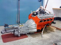
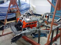
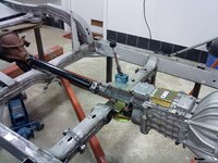


427Swede
Well-known member
I´ll continue with some more about the driveline alignment.
I used a very thin string to set the centerline of the frame from front to back.
It can be seen in the photo, it is orange. Using the string as a measuring base I could then measure the offset of the engine and the rear axle in relation to the centreline. The engine was offset to the right 25mm or, in english measurements, 1". This measurement was recorded at the front of the engine and also at the rear end of the gearbox (outgoing shaft). The engine is then parallell to the centreline and correctly offset.
Did the same operation with the rear axle, althoug it was more difficult to get accurate readings. Anyway, it was offset approx. 21mm (0,85") to the right which is the correct offset measurement.
Knowing that I had the centrelines correct I could finally fully weld the connection ears for the gearbox adaptor plate.
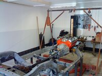

427Swede
Well-known member
The gearbox was then raised to a maximum position so that it would not hit the tunnel roof in the chassie. I could raise it 20mm (just below 0,85")
You will have to excuse me for not using inch measurements the whole time. It is just too complicated to understand... The metric system is way more logical to me. I do not mean to offend anyone, I´m just not used to it.
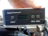
This operation resulted in an outgoing angle on the yoke of 2,8°.
I did a lot of testing with different positions before finally deciding to go with 2,8°, this angle will give the best compromise for my car.

427Swede
Well-known member
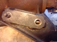
To get the rear axle outgoing shaft parallell but at an opposing angle to the gearbox yoke, it was necessary to modify the rear axle chassie bracket. It was not possible to just modify the bushing (poly or rubber) in the front of the bracket. It did not give enough movement to get proper angles.
It was rather easy to modify the bracket. When the axle was in correct position (at 2,8° upwards) I made measurements of where the new front hole in the bracket should be. Then I removed the reinforcement plates from the bracket, welded the old holes in the bracet and drilled new holes at correct position. Assembled the bracket to the axle and rewelded the previous removed plates in correct position.
The photo shows where the front hole in the axle must be positioned to get a correct angle.


