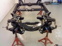
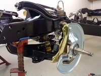
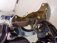
1969 427 restoration from Sweden

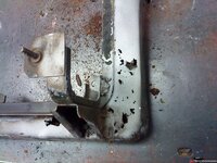
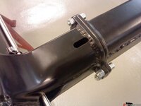
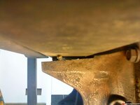
By tilting the front of the axle upwards to 2,8° from pointing down 1° means that the cross member that the axle is bolted to also is forced to tilt at the same angle and this will subject the frame connections and bolts to tensions not wanted. The photo shows the edge that is formed betwen the axle and cross member.

18774ed1690b7cd9d.jpg
 
I do know that it is undesirable to lower the rear axle since this might affect handling but, in this case it is only 3mm (0,12") and I´ll take my chances with this solution. If I see any bad effects I will get a new crossmember and modify it in the middle to get the axle a bit higher.
However, this solution (modified crossmember) also has a downside since this will most likely increase the working angle of the universal joints (of the cardan shaft) to or above recommended limits.

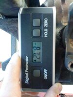
Anyway, here is the final 2,8° angle of the rear axle. (87,2-90=2,8°)
And the resulting angle of the cardan shaft was 0,6°. Unfortunately I do not have a photo showing the final cardanshaft angle.

18774ed1690c243b4.jpg
 
Last edited:
I have measured a few differential pinion angles and found them at about .5 degrees. I know this is not proper however these cars were all original. I speculate that the rear is basically mounted in the car (from the factory) at 0 degrees. Also, something to consider, why wouldn't a cardan joint be phased correctly if the car was setup like this:

ENGINE (down at the tailshaft X degrees) and DIFFERENTIAL (down at the pinion X degrees). \ ___ / (sort of like this)


I think this might be easier to do in a C3 (specifically a lowered C3). Hope this makes sense.
 
Last edited:
This operation resulted in parallell out going (yoke) and in going (pinion) shafts.
If a calculation of the resulting working angle for the universal joints in the cardan shaft is made with the previous measurements, the result is 3,4°.
I have double checked this by designing the driveline in my CAD system and taking measurements from the design.
But there is a second factor that influences the total working angle. It is the angle formed by the offset of the engine in relation to the rear axle.
It was difficult to measure this angle so I took this angle from my design and it is approximately 0,3°.
With this angle it is possible to calculate the total working angle.
The very thorough Germans at www.gwb-essen.de has a nice formula for this:
Vres = arctan x square root of (tan²x3,4° + tan²x0,3°)

In my case the final result is 4,0° at each universal joint. Recommended total working angle should be between 0,5° to 3,5° so, I´m above the maximum recommended limit...
If I raise the rear axle I will be even more out of the limit. But, I would think that a car that is not used as a daily driver will manage anyway. it will take a long time to wear out the universals. And I´ve got brand new hig quality Spicers:bounce::bounce:
 
I have measured a few differential pinion angles and found them at about .5 degrees. I know this is not proper however these cars were all original. I speculate that the rear is basically mounted in the car (from the factory) at 0 degrees. Also, something to consider, why wouldn't a cardan joint be phased correctly if the car was setup like this:

ENGINE (down at the tailshaft X degrees) and DIFFERENTIAL (down at the pinion X degrees). ___ / (sort of like this)


I think this might be easier to do in a C3 (specifically a lowered C3). Hope this makes sense.

Hi,
You are totally correct about the alternative arrangement. At GWB it is called a W arrangement. It will, as you say, give correct phasing. The W arrangement also has to have equal angles for the shafts to have correct phasing. It applies to the same basic laws.

It would be possible to tilt the rear axle more downwards. But this would also create bending on the cross member and a wedge will be formed and the axle must be lowered at the front of the cross member. The axle bracket probably won´t have to be modified. A thicker bushing in the front might do the job.

Thank´s BBShark for your input, it is a very interesting discussion!! Especially if one considers the original design and how the engineers at Chevrolet was thinking about this. The phasing problem was known back then as well.
 
Last edited:
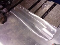
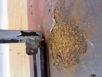
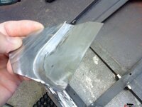
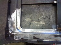
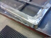
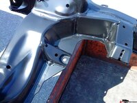
The frame is basically finished and I´m continuing with the only part on the whole car that was corroded by rust, the radiator frame. Only the lower parts were corroded and had to be renewed. Nothing special, a few pieces of sheet metal that I hammerd to correct shape and welded back.

The bad part of the frame, same on both sides.

18774ee12eebd6fa4.jpg

Nice pile of rust:cry:

18774ee12eec9c237.jpg
 
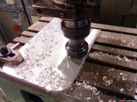
Had to manufacture new outside edges as well. New sheet metal from center of frame (at left side) round the corner and up about 200mm (8")
18774ee12eee804db.jpg
 
Last edited:
Time to dig into the trailing arms. Decided to do all work myself after a long consideration. Carefully read all articles by GTR1999 before I started work. it was very helpful!
The arms were in a mechanical bad condition. No rust what so ever thank God!
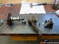
When I removed the first stub shaft I dicovered that the shims were positioned on the outside of the outer bearing (towards the drive shaft) :bonkers:
The second shaft missed all shims and also the distance tube between the bearings:bonkers:

18774ee12ef134615.jpg
 
Next step was to sandblast the trailing arms and measure the dimensions of the offset. It was all within specifications, well, almost. Had to make a small correction on one arm but it was very little.

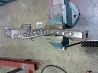
Then I fully welded them. As you know the arms consist of two pressed U-profiles welded together. Since the flanges of the U-profiles fully overlap each other it is possible to strengthen the arms further by welding the overlap together. This will give the "double" thickness of the steel at the most critical areas where the strain probably is higest.
Drilled a number of holes in the outer plate and welded them shut. This was made on both the up side and down side of the arms.

18774ee12ef17e58b.jpg
 
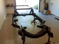
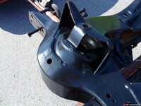
Continued with having the frame powder coated. 2 layers, 1 layer of zinc and one layer of semi gloss black. Each layer baked in an industrial oven at 200° Celsius.

18774ee7c04cc5623.jpg
 
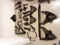
All parts were also powdercoated. Spent a few days grinding all sharp edges on all parts with a file before powder coating... Nice and smooth.

18774ee7c04b7f97c.jpg

18774ee7c224b137a.jpg

18774ee7c225625a0.jpg
 
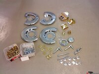
All bolts in the front suspension and rear axle/suspension were changed to brand new bolts. The remaining bolts/ parts were zinc plated. White and yellow colours were used.

18774ee7c04c29e1a.jpg
 
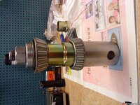
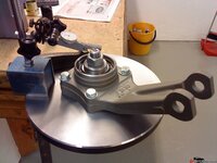
Machined a spindle set up tool and set the bearing end play to 0,04mm (0,0015") on both spindles. Before this I machined the spindle flanges to 0 runout in relation to the bearing seats. Had to remove 0,12mm (0,005") on both spindle flanges... Also mesured all shims for even thickness using a micrometer. Actually they were all perfect! I know that GTR1999 often finds shims with uneven thickness but I suppose I was lucky.
Of course I had thorougly studied GTR1999 instructions on how to do this job. It was not too bad doing this but I think I spent 5 evenings on each trailing arm to get them finished.

18774ee7c047956e4.jpg

18774ee7c0484513c.jpg

18774ee7c048e5b6b.jpg
 
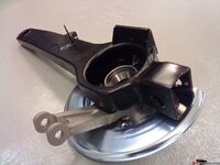
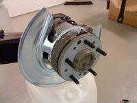
Finished and assembled trailing arm. I used poly bushings in the front. If they do not work ok, I will change to rubber.

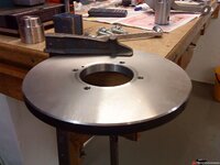
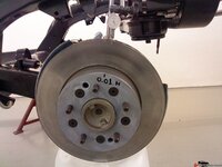
Machined the rotors before assembly and shimmed the runout to 0,015mm (0,0005") I used special stainless shims for this that I use when I need to set radial runout on parts that I machine in my lathe. They come in various thickness and are very easy to use.

18774ee7c04ad5100.jpg
 
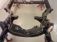
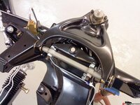
The rest of the frame was assembled with new parts from Moog and so on. I used poly for all suspension parts.
550 front springs, 355 rear spring. Bilstein shocks on all 4 corners and thicker swaybars. Hopefully I will have a Corvette with better handling than before:D

18774ee7c04d6565d.jpg

New fuel lines and break lines. Not one single line did fit. Had to rebend each one of them.

18774ee7c7ecafb46.jpg
 
Again, very nice work. I look forward to your posts.

Your shop looks as clean as a hospital room! Mine looks like a long abandoned warehouse (full of junk) :eek:
 
Top