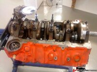
1969 427 restoration from Sweden

Test assembly of the ARP studs. Nice quality of the ARP stuff! Those of you with a sharp eye will spot a mistake mad by me in this photo...

187750280bf7975a3.jpg

Can you give us a hint?

4 studs have a shoulder for the splash shield, the 2 in the rear are not in the right location
they go in the middle to hold the splash shield

It was fixed in this pic.

187750280bf94395b.jpg
 
Last edited:
Yes Michel, you saw the embarassing misstake:clap:

Some more engine pictures. Assembly of cam gear and chain.

187750281054535e0.jpg

Determining the TDC with a home made tool.

187750280d4d3148f.jpg
 
Checking of camshaft against the cam card datas.
Everything was fine.

187750280d4d6218b.jpg

Timing chain cover and balancer assembled. Mr. Gasket timing tape fixed in correct position in relation to TDC.

187750280d4d907b8.jpg
 
Time to check the new springs from Comp Cams.
They were very even and only a few minor adjustments (washers under the springs is what I mean) were needed.

187750280d4dc2098.jpg
187750280d4df3d6e.jpg
 
Close up of the ´"not so fancy" rockers. The will do just fine on this engine. No need to by the expensive extreme stuff at this point.

187750280d4e8ffb8.jpg

And then the engine finally in place.

187750280d4ebed8f.jpg
 
Very good job, and no need to be embarassed, you did say "Test assembly of the ARP studs"

Thats why tests, mock-ups are done first to find assembly mistakes...

and by the way, you have a great work place,
 
Last edited:
be sure to check the slots on those roller rockers. This guy - http://www.bangshift.com/forum/show...-70-Caprice-Granny-s-Luxo-Muscle-Barge/page99 - has had to pull his motor apart twice because several of the roller tip rockers may be hitting the rocker arm stud and eating the lifter.

A quick way to check (as is implied on that thread) is to rotate the motor so each valve is at full lift; then put a wire from a paper clip between the edge of the rocker arm slot and the stud. If there isn't enough room, now, it's really easy to clearance them a bit so it doesn't contact.

Thanks for the tip SBG, actually this engine had a mix of standard slot stamped rockers and long slot stamped rockers (marked with an L) randomly assembled on the heads:crap:
All rocker studs had marks in them so I changed them, With this in mind I did check the gap of the Magnum rockers and it was ok. The Magnum rollers rockers were equipped with long slots and they should be fine with this camshaft that is not very high lifting.
 
On to the flywheel and clutch.
I ordered a SFI certified flywheel when i bought the Tremec TKO 600 gearbox together with a heavy duty clutch.
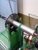
The flywheeel is made in USA and it is a well known quality brand. The instruction said to check unbalance before assembly, even although it was already balanced. Shown by a big hole drilled in the flywheel.

So, I started by measuring the complete flywheel in the digital measuring machine at my work.
With the guide diameter for the crankshaft as the reference surface, I measured runout of the inner diameter of the friction surface and the runout of the outer diameter (just below the starter ring gear) in relation to the guide diameter.
The result was quite shocking to me:shocking: The measuring machine showed a total runout of 0,002" (0,05mm) on both diameters in relation to the guide...
This means that the larger part of the mass on the flywheel is acting as an unbalance weight. This is really not an indication of high tech and quality in my world.
Of course, the unbalance is fixed by the balancing operation but it would be better to do a more accurate machining from the beginning.

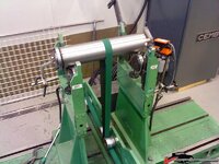
Well, I modified a balancing shaft that I had been using for snowmobile clutches with a small press fit to the flywheel guide diameter and balanced it to within approx. 0,1grams (0,00353 Ounces).
187750280e3d307b1.jpg
 
Tested the flywheel a couple of times and it showed an unbalance of approximately 5 grams (0,17637 Ounces). Not too bad! The unbalance was always in the same position which is good.
Drilled a few holes and tested a few times until I got it down to a steady 0,15-0,20grams (0,00529-0,00705 Ounces). Good enough for my engine at least.

187750281025e464c.jpg
 
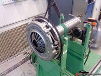
Tested the clutch on the balanced flywheel and after testing it in all 6 positions,I could determine that the unbalance varied between 5-25 grams (0,176-0,882 Ounces), depending on position. Tested the clutch at the best position (5 grams unbalance) to see if the unbalance was at the same position but unfortunately, it moves around betwen every disassembly of the clutch... This is caused by the too large bolt holes in the clutch. The only solution is to drill guide pins to the clutch and flywheel. On this clutch that is not possible due to lack of space.
So, I marked the clutch-flywheel position so I can reassemble iton the engine later.

I will have to live with this 5 gram unbalance but what the heck, it worked nicely back in 69 without any balancing:amazed:

187750280e3dc52e1.jpg
 
Last edited:
Cover installed. Spent quite a few hours checking/adjusting the run out of the housing guide hole for the TKO 600 according to the instructions.
Got it well below allowable tolerances so it should be fine.

187750280e3e59cfd.jpg

187750280e3e7aad5.jpg
 
Did a trial fit of the generator and all the drive belts. The Power steering pump was really difficult to assemble, even with the body off. Extremely tight to get the bolts in place...

1877503a73265c850.jpg

1877503a7325bdb2a.jpg
 
Top