SBG's C3

so, time to fix yet another issue - the brakes. I'm tired of the "will I have enough vacuum or not" issue with the motor; so I'm putting manual brakes on the car

IMG_0181_zps9eb59024.jpg

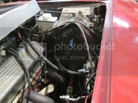
so I have to clear a hole
IMG_0182_zps546adc52.jpg

now is the time I mention I'm really getting tired of trying to fit my 210 lb chassis in the footwell

anyway

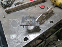
here's where I stopped
IMG_0184_zpsa059cf5a.jpg
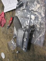
an adapter to eliminate the booster.... tomorrow, brake lines
 
interesting, it seems like we talked about this before... so how do you size the master cylinder piston and piston travel to get the full compression with the correct pedal travel? are there sizing guidelines or something similar?
thks bob
 
Yes there are - I have a spreadsheet on my other computer that I'll post up here tonight.

Though I have a question about the C3 system. It is beyond my pay grade to understand why the front (which operates the front brakes) brake line from the booster to the proportioning valve is smaller to the front wheels than it is to the rear. I intend (unless some explains to me prior) to change the lines to the proportioning valve to same size (and let the valve, not the pipe size change the amount of fluid the front brakes get).

I think someone made a mistake at SS brakes because the front line/rear line orientation on a C3 is reversed of what is "normal." Normally, the front reservoir feeds the front brakes, and the rear the rear brakes; but on a true C3 Master cylinder the line from the front then crosses to the back of the proportioning valve.... however, as the fitting size is different front/rear, it's impossible to screw up from my end. What is odd, in all of that, is the smaller line feeding the front calipers since there are more pistons in the front than in the rear.

Or I could be complete full of shit.... but everything I've read points to what I just described.


In almost 10 years of owning this C3 I never paid attention and I never noticed the front brake line is smaller than the rear.... I just went out to the garage to have a look.... Damn sure the rear line is bigger..... This assumes the rear reservoir is for the rear and the front for the front..... I did not look that closely :smash::smash:
 
I don't know how to attach an .xls file to vettemod.... this is a pretty useful tool; so maybe it can get posted up in downloads?
 
i sent you my email address for that file, i would like to see that.


I bet the line size has more to due with how fluid moves over distances and the bigger pipe going to the back has less residual pressure loss so the "pressure signal" front to back is more even, and the proportioning valve is controlling volume as opposed to pressure
 
Last edited:
i sent you my email address for that file, i would like to see that.


I bet the line size has more to due with how fluid moves over distances and the bigger pipe going to the back has less residual pressure loss so the "pressure signal" front to back is more even, and the proportioning valve is controlling volume as opposed to pressure

I agree with that analysis, but at some point the pipe size gets too small to effectively transfer the signal - with electrical wires, the light doesn't light and the wire burns up like a fuse.... in this case, I think the brakes just don't work.
 
I got the file thanks, maybe GM being cheap skates was trying to save a few pennies on each car every where they could hence the smaller tubing
 
well what we don't know is how their penny pinching ways leads to design decisions.....and seeing now about the key cylinder issues being ignored because it was too costly to change tooling is a real eye opener.....its all about dollars and cents to the corporate folks
 
so a bit more work done before small group this Friday night

the adapter installed
IMG_0186_zpsf915e8c7.jpg

bench bleeding
IMG_0185_zpsda2e3dbf.jpg

it's actually bolted to the firewall, just no picture of that yet...
 
A vacuum reservoir works. But, my 68 had manual brakes and those worked great.
 
so a bit more work done before small group this Friday night

the adapter installed
IMG_0186_zpsf915e8c7.jpg

bench bleeding
IMG_0185_zpsda2e3dbf.jpg

it's actually bolted to the firewall, just no picture of that yet...

Methinks you going to have to do your input rod length, just like I had to shorten the input rod on my Hydroboost in the '72.....PIA....


:surrender:
 
apparently I didn't take a picture, but that rod is the same length as the input rod to the dual diaphragm booster that I removed.
 
So I got the brake lines connected - but not bled, I'll have to have a friend come by tomorrow to finish that task....

first... length of the rod on the booster
IMG_0187_zpsb3d0ae1a.jpg

I should probably hold the camera steadier... but everyone's seen a non-power master cylinder

IMG_0215_zps21a3a3fb.jpg
 
Top