DRY SUMP PARTS RECOMENDATIONS - Please

phantomjock

Well-known member
Joined
Sep 2, 2009
Messages
1,824
Location
Retired Again!
I am getting restarted on a number of projects on "Elvira." This thread is focused on Lubrication.

She will be a full-time track-day/racer (occasional drive to AX site-so street legal). Concerned about high-G loss of oil pressure on track, I am considering a Dry Sump setup and need some pointers. I find limited discussion here. I note "back in the day" TT had some comments over on DC as did redvetrcr.
I'm looking to get some intel and help in what I should be considering. Hopefully some members here have done this and can provide guidance.

I found Aviaid https://aviaid.com/pdfs/064-wet_sump_and_dry_sump_oil_pans_for_SMALL_block_chevrolet_engines.pdf has a pretty good summary of bits and pieces - and price$. Also Jones Racing Products has a lot of gear that works on serpentine setups. I'm looking for preferences or recommendations.

Relevant items I currently have installed on my 383 SBC:
Canton Road Race Pan with big kick outs -- That would be replaced -- I note AL pans can be problematic with damage. So it might have to be steel/stainless steel.
New Mehling Oil pump - guess that comes out too
Remote Oil filter mount - keep that
MasterLube Oil Accumulator - not installed yet - but keep?
Seperate oil cooler and fan setup.
Steering will not be a problem as I'm moving to a front steer setup.
MOUNTING PUMP I'll be running the steering in manual mode - so the KRC pump comes off. No aircon either - reasonable mounting options - or is lower better? My motor is mounted with motor plates not engine mounts so I will no doubt factor that in.​

Grumpyvette has some good info on his site,
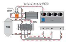
e-oiling-system-2019-04-18_18-08-01_869088-960x621.jpg
several images that clarify the function of windage trays, and a good schematic of Dry Sump flows, but I need some more specific ideas.

Like:
1. How many stages for the pump? 2, 3,4 - or 5? More stages is more $$, but if I save an engine it would be insurance. Minimum size for race configuration?
2. More stages gets more complex dry sump pan. Clearly the pan needs the same number of ports as the pump. Any specific pan recommendations? Also, I note in Grumpyvette's diagram, the return line is to the block and not the pan. Is there a preference?
3. I'm considering placing the storage/sump tank in the footwell of the passenger side. Good/bad idea?
4. What is the pre-start process? Complicated, or spin the pump to circulate the oil? [I'm in FL not Fargo! Would I need a tank heater on the tank?] Or start the engine and let it idle for 10 minutes until temp/pressure are reached? Or would a charged accumulator resolve any pre-start issues?


Or am I over thinking this--Just buy a kit and bolt it all on?

I've seen a few YT videos and looked for DIY dry sump setups - but no luck. Any links would be much appreciated.

Thanks In Advance.

Cheers - Jim
 
I have an aviaid 3 stage with 2.5 gallon tank. I’d say it’s nice entry level equipment. The pump is very nice, but the pan is pretty basic when you compare it to a Daly or Petersons. (I think pappy has one of those two)
Anything from jones racing is awesome, love their HTD pulleys (radius tooth) and they are very easy to talk to if you need something custom or just help configuring a drive setup.
I was told that as long as your pump is lower than the tank, it will prime itself for start up.

Due to packaging on my car, I chose to run a separate oil cooler thermostat. The thermostat/remote filter combo seems like a good way to save some $$ on AN fittings if you have the space. I’ve got two double pass coolers and an oil thermostat from Improved racing... looks like very high quality stuff, but again, no run time on them yet :suspicious:
6155c44eef4d08e6.jpg
 
Hey Jim,

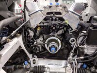
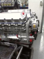
I have always been a fan of Peterson, but this time I went with a Dailey pump and pan. I have a short stroke big block (so lots of rpm), so I chose a 5 stage pump (4 suction and one pressure). I also have the Dailey air-oil separator on the back of the pump, which causes problems (due to length) with standard side motor mounts - but is no problem with motor plates. I am using the Dailey signature billet pan that has the pump bolted directly to the side of it. This eliminates the scavenge lines since the pump draws directly from the pan. The pump sticks forward of the block about six inches, so you have to consider that for space. I had Peterson build my tank. Taller is better for head pressure (just over 3 gallons). Big suction and feed lines (-16) are good and you need a good sized vent line to the vent tank. I use a -16 there. You need a 100 micron filter in the scavenge line to the tank for debris, and a normal filter before the feed line goes into the motor. I run an oil heater in the tank so I don't have to get the water hot trying to warm up the oil before a track session. I run a Jones cogged belt drive and power steering pump. There are better photos of the dry sump pan/pump in my build thread. (http://www.vettemod.com/forum/showthread.php?t=11526&page=2 Post 13) This site would not allow me to re-post them in this thread.

Dry Sump Tank 2.jpg

Motor 4.jpg
 
Last edited:
you can scavenge oil from the valley in addition to the pan, you can also run your cooler on either the scavenge side or the pressure side, if you look on ebay you will see whats called a segmented pan (basically dividing the pan into 4 separate sections, each requiring it`s own scavenge stage), a good oil pump will create a vacuum so you can seal the valve covers (NO vents) and vent the tank only, on my racer I mounted the tank behind the passenger seat area to keep it away from the heat, that might be a problem with a stock rear floor. in my mind the diagram shown makes no sense on the pressure "out" side of the pump (through the paper filter and the cooler off one line?) it also shown no screen filter (I had a Canton with a coarse screen) and don`t add screens to the pan they can get plugged with bits of silicone, use a screen filter. -12 lines are good a -16 from the bottom of the tank to the bottom of the pump is good along with -16 or a -20 vent off the tank, I did run one -10 oil line to scavenge the valley, my black had a provision for that, also know in advance your header tubes might be right where the scavenge ports are on the pan...my car is gone but looking at some very old not great pics I ran my paper filter on the pressure side along with a temp gauge and valve cover oilers and the cooler and coarse screen filter on the scavenge side
 
Last edited:
Excellent advise from folks "in the know." This is the best forum!
Thanks to all -- and Thanks to TT for getting it started.

Cheers Jim
 
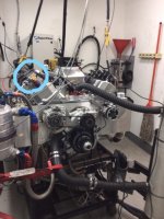
As Redvetracr pointed out, a good dry sump pump will build vacuum in the crankcase. Depending on the size and efficiency of the pump, that vacuum can be significant. Make sure you have good seals. After watching the vacuum on my motor on the dyno, I decided to run a -12 line from one valve cover to an adjustable vacuum pressure relief valve. Then I continued the line to a check valve that would open if the crankcase developed positive pressure - this sometimes happens with a rapid throttle chop. The line then goes to the top of the dry sump tank as a vent line. Below is a photo of the vacuum relief valve that we rigged up (not the final configuration) during the break-in dyno runs when the vacuum was getting pretty high. Didn't want to suck the seals into the motor - LOL. The -10 line running into the top of the dry sump tank is the "air" line from the air-oil separator. The separator is a centrifugal device on the back of the pump that separates most of the air from the oil after scavenging and sends it to the top of the tank. Dailey has a good youtube video showing how effective it is.

Motor on dyno 3_LI.jpg
 
Last edited:
Pappy -

That too is great advice. The whole lubrication system calls out for system integration, and that is why I'm asking our user/experts before heading out on a parts safari. Been there to often on other sub-systems of this build. :blush:

I may spend some phone time with one of the parts purveyors to see what their build ideas are too.

I might wisely :
1. Get Smart
2. Create my draft specs
3. Hire a competent builder/sort out the details/buy parts
4. Watch intently and ask a lot of annoying questions​

There is more than one way to throw money away (did I hear you say mission-creep and cost over-runs)? :D

Cheers - Jim
 
I'll add to redvetteracer's note -

It looks like the Dailey pan that pappy has installed is segmented - and quite a novel means of scavenging the oil with the built in galleys. I do now have a header conflict (partial reason for this path + added performance/longevity)

I'm liking the pump integrated into the pan. Less stuff hanging around; hoses, brackets, etc. It also looks like it will help aid potential header clearance issues.

Empty cockpit, so placement there will be a good option on the passenger side. More hoses to run, etc. but clears the engine bay. May wait on exact placement until I get out the scales again. Oh yeah - and open the wallet!

Cheers - Jim

Jim,

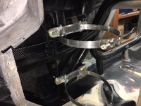
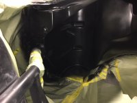
For the tank, I built a recess in the firewall (fiberglass) under the cowl on the passenger side - just aft of the back of the motor. I have an access door on the cowl to reach the tank cap. The back of the fiberglass recess intrudes into the passenger footwell, but it keeps the tank and its hot contents out of the passenger compartment. That tank location keeps the plumbing pretty short and direct. The first photo below is with the firewall cut out. It shows how I mounted the tank straps to the underlying cage bars. The second is the recess finished. The straps bolt through bosses in the fiberglass to the cage weld-nuts behind it. Hope that makes sense.

Dry Sump Mount 3.jpg

Firewall Jul 2020 8.jpg
 
I've had a long relationship with the folks up at Coleman Racing, so will be working some of the bits from them. They deal Champ pans and are quoting a 3 @12AN setup for me, to meet the left side requirement (spacing is driven by the headers). Also shallow (4 1/2") deep same reasons.

Off the crank, I am planning a 4 stage pump and alternator only Everything else is 12V. I'm figuring this all out [with a lot of you guys helping]. My local shop is "slammed" and can't get me in til late Spring! So, its on me [and you guys--THANKS!]

Chris - just wondering what ratio are you are running from your Crank to Alt. I'll have a 28 tooth alternator pulley. What size/tooth count Jones are you set with on the crank? {I can't read a PN - so have to ask}

Coleman Racing suggested if I was just running short events that 3 gallon tank would most likely be sufficient. I'm leaning to a 5 - just to make it more difficult to install! Thoughts?

Cheers - Jim
 
Coleman Racing suggested if I was just running short events that 3 gallon tank would most likely be sufficient. I'm leaning to a 5 - just to make it more difficult to install! Thoughts?

Cheers - Jim

Jim,

Bill Dailey once told me that he would rather have 2.5 gallons in a taller tank than 4 gallons in a short, fat tank. His comment was based on head pressure and better de-aireation of the oil. I think more volume is better for oil cooling, if you need that. I opted for a 7" diameter tank that is 21 or so inches tall - holds just over 3 gallons. I also have a big oil cooler that holds quite a bit of oil.

Pappy
 
Pappy -

I was looking at the Z06 tanks as an idea and thought, hmmm - that might be an approach. Makes good sense from a lateral G loading too. Footprint is just like you mentioned, a narrow (but taller) tank is a little easier to situate. Haven't sourced a tall narrow tank yet - but that is now a focus. Oh yeah, I need to mention nice CF work on your install BTW!

I also plan on a cooler - already have one the shelf so that will be in the system too. It will still have to find a "favored" side left/right, but there will be a place.

Thanks and, Cheers - Jim
 
Chris - just wondering what ratio are you are running from your Crank to Alt. I'll have a 28 tooth alternator pulley. What size/tooth count Jones are you set with on the crank? {I can't read a PN - so have to ask}

Cheers - Jim

The water pump and crank are 1:1, I forget what the alt is and the car is still at the fab shop... I’ll have to see if I can dig up some records. 1:2.75 is in my head for some reason...
 
.. I’ll have to see if I can dig up some records. 1:2.75 is in my head for some reason...

Chris - I'd bet that might be close. Don't work too hard on finding the details. I probably don't want over 16-18K on the alternator, and with max 7K on engine >> 16/7 = 2.28 ; 18/7 = 2.57 (16/6 = 2.66)

Thanks and, Cheers - Jim
 
Lifter Valley Questions/ideas Please

So an update is due.
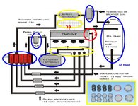
Forgive the schematic but too soon for real pics!
1269600f31d91f0c0.jpg
I have on-hand the following (circled in BLUE):
5 stage Dailey Dry Sump Pump
Peterson Remote oil mount with primer
Peterson 3 Gallon tank
Oil Cooler + fan
And just ordered (circled in YELLOW):
Kevko 3 Scavenge port low profile pan
Lifter Valley Baffle (pan)
Milodon lifter valley screen ports
The wet sump pan and oil pump are removed. The oil pickup post is now blocked and the drive for the oil pump removed too.
The intake manifold is not yet installed, which brings me to my questions (RED):

1. I see a number of references to adding lifter valley breather.standpipes to the 8 drain holes in the SBC lifter valley.

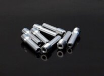
pow801060_600_2.jpg
I guess this is to raise the oil level to be scavenged? Should I get and install breather/standpipes? The Mildon kit includes 1/4" NPT plugs as well as screens so I may have another option to the breather tubes and block off those "drains." What is our community experience for the lifter valley?

2. I guess the "smart" idea is to use the 4th pick up to scavenge oil from the lifter valley. (see red on diagram) I keep reading; "Do this" but not, "Here is how to do this." I think I have found a reference to doing that - but ask for your thoughts. Since I am using a crank trigger setup, I might be able to have a piece machined to mount through the exiting distributor hole to scavenge the lifter valley. (Screened naturally) Thoughts on this approach please!​

Appreciate everyone's patience and advice. My engine builder has no experience with Dry Sump systems, so I'm kinda solo here.

As I get things organized and really started, pics will follow. [And, clean up the garage too!]

Cheers - Jim
 
Last edited:
I’m interested to see more about the lifter valley pan/plugs. If you’re doing a crank trigger, doesn’t your ecu need to see a cam position as well? And to go along with this, I believe the distributor plays a role in the oiling passages through the block.
I’ve got drysump envy already and you haven’t even shared any pics! This place is dangerous to my wallet :gurney:
 
Yeah its the oiling through the passages I'm "concerned" about. And yes, "Cha-Ching" is the sound it all makes. Once the cam timing is set (gear drive - no chain), the crank trigger and the ECU are independent and replace the Dizzy. Its an Electromotive system I've had on hand a number of years. No timing advance from the dizzy required. I'm even removing the vacuum lines from under the manifold on the Webers as that won't be needed - as far as I know. No brake or transmission pull off either.

I've done a lot of looking yesterday and today (online- crappy weather here and the garage too cold to work in). At one point had over 30 tabs open on the browser - and that was just Yellow Bullet and Bang Shift! Pulled over 60 pages of just paragraphs on set up from those sites. Then add in Grumppyvette, Lateral-G, Pro-Touring, etc, etc. Soon to have it boiled down to maybe 10-15 pages. More words then. It won't be from experience - just research.

Good news, they shipped my pan today, so maybe by this weekend I can do some assembly. (and pics too).

Cheers - Jim
 
thats a long pump, sure it`s going to fit in front of the motor mount stantion? did you have Kevko (Kevin right? he worked on my oil pan) place your bungs far enough away from your headers and not in the middle? and finally you can scavenge out of the valley with a smaller (I used a -10) hose.
 
your yellow "screen optional" should be screen filter IMPORTANT, I used a Canton/Mecca remote style with a coarse screen, oil cooler can be on pressure or scavenge, I ran it on the pressure in front of a remote with a paper filter. hoses to and from the tank -16, everything else (except for the valley scavenge) -12
 
hopefully you already know you need to block the unused oil passage above the old oil pump mount, tap the rear main of put a plug in the block under the rear main.
 

Latest posts

Back
Top