DRY SUMP PARTS RECOMENDATIONS - Please

Just the kind of information I knew resided here!!
1. hopefully you already know you need to block the unused oil passage above the old oil pump mount, tap the rear main of put a plug in the block under the rear main.
CHECK! Accomplished.

2. your yellow "screen optional" should be screen filter IMPORTANT
CHECK! Arrived in yesterdays Big Brown Truck

3. oil cooler can be on pressure or scavenge, I ran it on the pressure in front of a remote with a paper filter. hoses to and from the tank -16, everything else (except for the valley scavenge) -12
COPY ALL - My Remote is the Peterson Remote + Primer

4. thats a long pump, sure it`s going to fit in front of the motor mount stantion? did you have Kevko (Kevin right? he worked on my oil pan) place your bungs far enough away from your headers and not in the middle? and finally you can scavenge out of the valley with a smaller (I used a -10) hose.
Will be fit-checking pump mount this weekend. Will take some mods I bet. Also need to sort out the pulleys too. Yep--Kevin @ Kevko. Easy to work with and inexpensive. Pan should arrive tomorrow along with a baffle plate.

Looks like will be a -10 through the (now) unused vacuum port on the intake manifold. Seen here:
12694f4cb7d7a5094.jpg

I'm starting to "waffle" on the Valley "breather/standpipes". I have a roller block (so roller lifters) and understand the valley drains can be closed off and not cause harm. But my Crew Chief reminded me we'd local drive to AX events, so might that be a concern? Or just put it on/in the box and tow anyway? Good thing I have all the smaller screens from that Milodon kit.

Thanks for the excellent advice! Very much appreciated.

Cheers - Jim
 
Getting parts organized and my plan sorted out. Still a few questions keep popping up. Still focused on the Dizzy and the Dry sump with Electronic Ignition. (You can spend almost as much in fittings and hoses as a pump!)

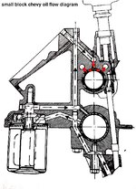
Here is a quick pic of the SBC oil flow schematic (general): sbcoiling-jpg.jpg
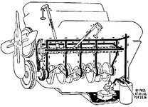
Now, that is a simple diagram and probably leaves out a lot of detail. But, it does show the shaft from the Dizzy down to the pump n the pan.


So, as I figure, the distributor is turned by gear on the shaft as the cam sping. In turn, the shaft spins the oil pump in the oil pan (wet sump system). Other than that, I don't see what the distributor shaft does for oil distribution: WC79vIM.jpg

It seems that a Dry Sump System will accomplish all of that - without needing a distributor shaft (or oil pump in the pan). So, as a question: Do I have that right?

To keep from blowing oil all over the engine bay (and track) I already have one of these:
Jesel_Distributor_Plug__96448.1557253836.png

To feed the engine, I'll use one of these and just plug the port (the one on the side) on the remote plate I have already. It is the center that "feeds" the block.
4251579ERL_L_22c56c4a-0778-4ea7-aa69-8cc1e13e9577.webp

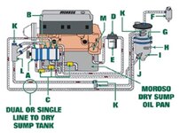
That had me looking again... for other details, and this one image is particularly good:
OIL_SYSTEM.jpg
That one is from Pit Stop USA (via MOROSO) and they have a pretty good reference with all the bits and part numbers (although it doesn't have a Lifter Valley scavenge included. Not much written, but overall seems like a good starting point -- if I didn't have all your support too!
Thank you :thankyou: THANK YOU!
(In hindsight, had I found that - I'd have had fewer questions. Too soon old - to late smart!)


Cheers - Jim
 
I don`t care for those (oil in/pressure side) adapters, in the old days we drilled the block just above the oil filter, the new race blocks are all drilled above the water pump, I also don`t think the double scavenge into the tank is necessary, I`m pretty sure I ran a -16 as most of what your pumping out of the pan (scavenge) is oil and air also vent the tank to a vent can using a -12 or better a -16
 
What are you using for an ignition system. With my Dailey Dry Sump I still have a distributer, but its only purpose is for the cam shaft position sensor. I run a crank trigger for ignition. I have a five stage pump that feeds a -16 scavenge line to the dry sump tank. I also have a -12 line that comes off a centrifugal oil-air separator that is driven off the back of the pump. It feeds air that is separated from the oil to the top of the tank. Then I have a -16 line off the top of the tank to a vent can. There is also a -12 line from one valve cover that passes through a vacuum relief valve before it goes to a one-way pressure valve and then to the top of the tank. This valve makes sure I don't have so much vacuum that I suck the seals in and the pressure check valve takes care of any inadvertent pressure spike in the crank case caused by things like a throttle chop. You are right - you can spend thousands on all of the plumbing and fittings.

Pappy
 
Pappy;
it's an ELECTROMOTIVE XD-I/2.
favicon.ico

I've been setting the engine up as "old/new-school" semi-tech as I can figure. So, its an electronic ignition, Weber 8-Stack, Cloyes gear drive and now Dry Sump. Any upgrade could be Hilborn Injection in lieu of the Webers. No fancy cam/valve train, the ignition triggers off the crank, so the cam is sort of "set and forget." Getting the timing right for the carbs will be a "thing" and no doubt a chore. But (hopefully) that will be rewarding -- I still have hope!

This from manual: (a few years old - I bought the system 10 years ago)

1.2 High Resolution Single-Crankshaft-Sensor Decoding
Some OEM direct ignition systems use both a crankshaft and a camshaft sensor assembly, making the
system more complicated and more expensive than it needs to be. Other systems use low resolution, four to ten
tooth trigger wheels on either the crankshaft or camshaft; these are not enough teeth to assure that the coils are
firing without timing errors. The XDI-2 solves these problems with a single, high resolution, 60-minus-2 tooth
crank trigger wheel. This affords resolution unheard of in any other electronic ignition available today, offering
spark accuracy of ¼ degree of crankshaft rotation. This accuracy makes the system ideal for the most
demanding engines.​

Clearly, the advantage would go to a variable valve train and turbo - but not on this effort.
I like the idea of your vacuum relief valve. I think you mentioned that before. It has been on my list to figure out. By chance, you have any part number or available link? Seems like a useful addition and I'd rather be better safe than face repair/rebuilding.

As as adjunct, I've been designing (that old engineering habit of mine) an air/oil separator. The new 3D printing revolution offers a (relative) inexpensive method for my madness. [No, I haven't bought one -- yet.]

redvetracr:
Very impressive collection of fittings. I have a smaller collection of mostly black and silver -8 and -10AN for fuel system, but no -12 for the dry sump setup. I will soon!

I like your idea of drilling the block, and may use that on the "spare" engine (its a circle track 355) sitting in the corner. Then I can also drill for the lifter valley scavenge and tap the inserts. It needs a build anyway. But, first things first.

I am running a single return to the tank from the pump - but my Dailey pump is set up with a -20AN fitting. Wow! there is some change! 30 bucks a foot. You can bet I'll be placing the tank close to the pump, and measuring carefully.

Hopefully next week (weather is improving), I'll get the oil pan coated; then installed, and start on some more bits for this segment. More parts to arrive early next week too. Pics will be included.

Cheers - Jim
 
Jim,

For the vacuum regulator I used the Peterson Fluid Systems Vacuum Regulator 08-0455. You can get them through Summit.

Pappy
 
Dry Sump Oil Cooling:

I've started the Dry Sump install. Yesterday, I got the Kevko pan installed. Lying on the creeper (car on QuickJacks (with stands!) it was a treat using the Fel-Pro snap-ups. Hats off to their design team for that. Not much to see - so no pics.

Now - on to the question at hand.

I know I included a cooler in my plans (and have one on the shelf).

Then, I just read (OK never trust the Internet) that because dry sump systems are so good at cooling the engine, that the engine has a hard time getting to temp.

So, it was suggested that running a separate cooler will not allow the engine to get up to temperature as quickly as it should.

Thoughts and experience welcome.
 
you installed your Kevko pan, did you plug the rear main or the oil passage just above it? if your doing any real racing an oil cooler is in order if not you probably don`t need it. I talked with Bill Dailey about oil tanks, I asked "whose tank do you like" none he said but buy a Patterson, I used a 4gal that had two rows of oil/air separators with the holes pulled in the top baffle, Patterson told me they don`t do that anymore (too costly) he also said to add a third baffle which we did...that tank along with a number of other parts went with the car when I sold it, I was sorry to see them go but they paid my number for the car so I can`t cry about it. my tank was mounted behind the sheet metal bulkhead behind the pass seat area, beware where you mount yours, close to headers will absorb heat, too close to the driver the driver will get the heat...
 
redvetracr:
...you installed your Kevko pan, did you plug the rear main or the oil passage just above it?
s-l400.jpg
I believe I did. I forgot to check. It may mean I drop it to verify. Oh No - One step forward...
I can guarantee I ordered it and it arrived in January.

The intake manifold is still is off, so I think I might run an endoscope down the dizzy "Hole." I might be able to see it blocked off.
Or, pull the drain plug in the pan - and get "eyes-on" with the 'scope from there. Now, I just need to find that 'scope.

I've seen a couple of engines (online) with this setup:
632AADrySump-500x476.jpg

I like the position - but of course that location is "at risk." I've the room with the engine moved aft - even with the radiator box. More so there, than at the firewall - or in the cockpit. And, save some $$ on the AN20 hose!

Off to look for the 'scope and check the plate is installed!

Cheers - Jim
 
thum_126961377a32833c2.jpg

That view is from the lifter valley down the dizzy hole...

Haven't looked from the drain plug side on the pan - but don't think I need to. When I pushed the endo/bore scope deeper I heard the telltale, "dink, dink, dink" from -- the oil pan! ARGH!

1. Find the part
2. Pull the pan
3. Install the part
4. Reinstall the pan​

There is some "fuzz" between the 4 and 6 o'clock position - will check that out too.

The saving grace ( I think) - this engine has never been fully oiled or run, so at least it not a mess like it could be.

Cheers - Jim
 
Every Picture tells a story:
thum_1269614a4a609c51f.jpg

It was already installed. So, now I have a spare for the "spare" engine! Now, not to lose it.

Cheers - Jim
 

Latest posts

Back
Top