Circuit design: protecting LED tail lights from transients

I found a good application note from Analog Devices that addresses the subject.
Automobile Tail Lamp and
Brake Lamp Controller


It utilizes there AD8240 integrated circuit to simplify the design

Bullshark
Thanks
Interesting find Bob, since you know I know someone at AD.
But don't you think this device is not that integrated, take a lot of external component to work, like the PWM generator which is usually integrated.
I'm waiting my buddy at AD to reply.
 
Update :
After a lot of talking and searching, here's the results so far.

1)here's a lot of stuff you have to prevent on a car system if you want to make it right :
-Voltage spikes, up to 50v
-Voltage reverse
-Voltage variations
Plus on the led side, a open circuit detection, to prevent domino effect when one led burn.
Dunno if I'll fit all the bill, but I'll tried.

2)I would simplify my schema if I make the driving and the brake light a simple group of led than would be drivent a different intensity depending of the case.
But I'm concerned about the aesthetic aspect.
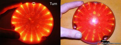
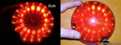
My led have a very narrow beam that draw a distinct pattern on the bubble cover
16554d7eeeb2c0c74.jpg
16554d7eeeb15a372.jpg
16554d7eeeb1f1998.jpg
(pics for last year experiment, the center part was not implemented)
So I would be loosing the wow factor led are also about.


3)There is a lot of existing automotive IC solutions, from several chip maker, but it's not for the retail market, got to buy by the hundrens.
I may ask for sample... why do I fell it's like cheating to the DIY philosophy?

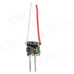
4)There is a lot of preassembled current drivers board, for the home ligthing and led maglite market. They're robust, tiny, and dirt cheap 2.20 w/shipping:
sku_13553_1.jpg
http://www.dealextreme.com/p/mr16-1...egulated-led-driver-8-40v-input-13553?item=34
They are pretty much the default impletementation of this chip :
PT4115
They can be hooked to a PWM signal too.
 
*Update*
After weighting up the all the factors, here's the updated plan :

I will be using very high intensity led, like those :
cree-led-400x400.jpg

All full power, they're simply blindingly bright.
I'll run them in a star configuration, one center white, for the flashing light, 6 red around for running/brake light.
I'll will have to run them with PWM anyway. I prefer to make them too bright and dim them down rather than having an underperforming system.
PLus, those are the very lights the drivers I posted about last thread are designed for.
At full rate they output heat like crazy, to the base of the light will maybe have to be made of solid aluminum to absort the heat.
Full power only occurs when braking, so I know my worst case scenario onmy occurs temporary.

Or course I'll be using the same lights for brake/run (with dimming), because let's face it, it save a LOT of complexity.

I could possibly get away with the PCB making idea for the leds, glue/solder the star shapes on the support, run a couple of wire between them and I'm golden.
One PCB should be required for the surge protection system,the current drivers and the PWM dimmer. Not sure I will integrate them in the tail light or regroup them all in an exterior housing.
 

Latest posts

Back
Top