Measuring air flow changes through the radiator after adding splitter and air dam

Larrywalk; Those flaps have been missing from my car for as long as I’ve owned it. I’ve thought about replacing them just never got around to it. I’ll try and get that tested once I get the car going again. I make the same round trip each test run, 6 miles than turn around and come back on the same rout.
 
With all of the mods people do to increase airflow to the radiator area, I think you can pass the point of increasing performance, and begin to force too much air to the radiator and under the hood which begins to create lift. I would think you want the LEAST amount of air that the car can handle without overheating. I put my front license plate on to reduce air going though the front grills (and to keep the cops away ;)), and I put the rubber flaps back on that cover the lights in the grill when they are down. So I have very minimal air entering through the grill. The majority of my airflow is from the bottom. No overheating, and less air being forced under the hood.

Ive been wanting to do a heat extractor setup for my radiator too... Ive also been wanting to add those greenwood (?) fender arch vents. I think they would be a pretty big help for cars that dont have pace-car spoilers to block off the front wheels.

I agree with your sentiments. I haven't had an issue cooling my engine, and have scrounged up some plastic material to (completely) block off the headlight grille areas to reduce the air into the pre-radiator area.
I've kicked around for quite a while plumbing up a manometer to measure the relative pressure levels of the engine compartment and the front wheelwells. My suspicion is that my pace car spoiler is diverting the air slightly outward in the wheel area, possibly causing a slightly lower pressure that can pull air out of the engine compartment (and brake areas). I'd like to know for certain if my suspicions are correct.
 
I haven't had an overheating problem, but my suggestion was motivated as to how to improve engine bay airflow to lower carburetor inlet temperatures
 
This is an interesting thread on a topic often overlooked. Some photos of your radiator and fan set-ups would speak volumes.

My 79 L82 with the original front spoiler and fan shroud set-up always ran hot, 230* on the highway. The radiator was only five years old and with no build up of deposits inside.

I went through considerable effort to install a four row aluminum radiator. It was advertised to cool 800 HP with an auto trans and a direct fit for a 79 Corvette. It only cost $300 from an ebay seller of radiators. It wasn't a direct fit, the radiator trans cooling bungs are not compatible and it required much modification to fit the space. That said, the new rebuilt engine has not been installed and I am already having concerns about its cooling efficiency.

It is a little thicker than the original radiator and the smaller, high density cooling fins will offer additional air flow resistance. It will have dual, 2600 CFM puller fans with a good rubber seal. In front of the radiator will be the AC condenser and a stand alone B&M 8 X 11 X 1 1/2 20,000 BTU transmission Super Cooler.

The license plate area was opened up, following BeeJay's example. Does anyone have any comment on how this four row aluminum radiator should work cooling my 425HP 355 engine? Since I need to use a stand alone trans cooler, I have been thinking a universal two row aluminum radiator, with large cooling fins, might actually do a better job for my street/strip application. Comments?
 
Mike, it's almost GOTTA work grand, I have a single row aluminum/plastic core thing the same core size as my '72, from a late F body V8,.....and backed up pretty close, is a set of Dual Spals....as DeWitt sells....just a normal on/off control relay via the injection computer.....

my engine is about the same, but now going to smaller cam, and so down on hp...but have been pushing 400 hp 355 roller engine for years now....
no problems....

so I think you got more cooling than I have....by a fair margin....I wooden sweat it man....

:drink:
 
Does anyone have any comment on how this four row aluminum radiator should work cooling my 425HP 355 engine? Since I need to use a stand alone trans cooler, I have been thinking a universal two row aluminum radiator, with large cooling fins, might actually do a better job for my street/strip application. Comments?

I've not seen a 4 row aluminum. I have a 2 row Griffin with 1.25" tubes and it's a pretty thick radiator. What brand and model? What size tubes?

Never saw a 4 row either.
Smallest alum tubes I've seen are 1" x 2 (most including Dewitts) then 1.125" x2 or 1.5" x 2 which uses a tank size of 3-1/2"

With a wider radiator, you may want to consider a better pump like a Stewarts stage 2 that has the internal bypass blocked off to keep the coolant velocity up. More tubes = lower velocity.
I ran for a couple years with a 4 row brass and no chin spoiler or radiator rubbers at tstat temps south of you (but lower hp).
 
images as promised

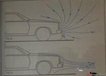
Here are a few images to review and digest. Sorry for the quality - handheld digicam and a sheet of glass to keep flat If I can source a scanner will update.
But you'll get the idea.
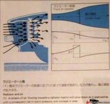
First one is Airflow through inlet, radiator and engine space.
thum_12694d212c6b2a6c8.jpg

Next is a diagram of flows when sitting vs moving - thum_12694d212cbfb3e84.jpg

Ford did some tests and the results are interesting if not somewhat dated -(Mustang and Pinto!) too big will resize tonite.


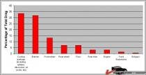
Is this all important? Here is a drag summary chart I found somewhere. Wish I knew looks interesting:
thum_12694d212d7813bda.jpg

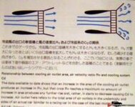
Air exit strategy is important too:
thum_12694d212dceca9eb.jpg

Hope you find those interesting. The 4 core vs2 vs 3 and 1 pass vs 2 pass will be interesting discussions too. Looking forward to monitoring ths thread.

Cheers! Jim
 
Does anyone have any comment on how this four row aluminum radiator should work cooling my 425HP 355 engine? Since I need to use a stand alone trans cooler, I have been thinking a universal two row aluminum radiator, with large cooling fins, might actually do a better job for my street/strip application. Comments?

I've not seen a 4 row aluminum. I have a 2 row Griffin with 1.25" tubes and it's a pretty thick radiator. What brand and model? What size tubes?

Never saw a 4 row either.
Smallest alum tubes I've seen are 1" x 2 (most including Dewitts) then 1.125" x2 or 1.5" x 2 which uses a tank size of 3-1/2"

With a wider radiator, you may want to consider a better pump like a Stewarts stage 2 that has the internal bypass blocked off to keep the coolant velocity up. More tubes = lower velocity.
I ran for a couple years with a 4 row brass and no chin spoiler or radiator rubbers at tstat temps south of you (but lower hp).

I still have the email from the seller 'KoolRadiators' on ebay, but the ad was taken down, so info gone. It was advertised as a four row aluminum direct fit in a Corvette including model year 79. I do not have particulars on the tube diameter or anything beyond the sellers claim. The radiator manufacturer is Champion. It appears well constructed, but not a direct fit. I am using a fully accessorized serpentine system from a 94 vintage Camaro. I already have an Edelbrock aluminum, reverse flow water pump to circulate the coolant. At this point I am beyond no return, so will have to see if it will do the job. In retrospect, if I had known the radiator trans cooler bungs were not 3/8ths NPT and couldn't be used, I would have gone with a universal fit at $100. They are 3/8ths inverted flare and the threads are very loose to a 3/8th inverted flare carb fitting. The top bung required a 90* to clear the top control arm cross shaft. There is nor 3/8ths inverted flare fitting with a 90* angle made and it would cause more restriction in the line flow. Hence, the required stand alone trans cooler.

Sorry for the long story, but I am hoping the cooling system I am using will keep the engine below 190* and the stand alone trans cooler keep the trans below 180*. The trans will have a temp gauge bung welded in the pan to monitor temps. If necessary, I will use a fan assist trans cooler.

phantomjock, thanks for the charts, they make sense. There is a short story in June 2009 Hot Rod under PIT STOP and titled Solving Cooling Woes pg 124. It has a chart showing flow with a spoiler and similar to what you diagram shows. It also describes why a two row radiator with large tubes is more efficient than a four row in dissipating heat. This is why I am concerned.

Gene, the one row, large tube construction of your radiator could actually be working in your favor.
 
Last edited:
........................... Right now I'm designing an airbox for my radiator, but the radiator will be in a forward laydown profile - not OEM aft leaning. I plan on a large-ish exit through the hood - like a few of the vehicles here. I'll load some pics this weekend - thats the soonest I'll have time to find-em!

..................................

Cheers - Jim

I'm not following how you're packaging it all, given that the hood front eats up a lot of the forward space when it is flipped open.
 
Well I've got the motor back together and the carb is just about dialed in so its time to bring this one back to the top.

I was having trouble getting reliable readings from my data logger so I had to do some digging. I found the sensor wire connected to the ground instead of the hot wire. Today was my first trip with it connected to the logging software and looks promising. I'll have to dampen the input but I think the software has that capability so it shouldn't be hard to do.

I'll have to put a switch in the temp sensor line so I can shut the fans down while driving. I was able to make a 10 mile run without the fans coming on but once I stopped and they came on they don't shut off. Its 92* with 60% humidity today so its hot. I think with the right fan switch the fans would shut off, my off switch may be a little low with the T-Stat I'm running to shut the fans off on a 90* plus day.

The first run shows that the fans just start turning at around 45 mph and at 50 right at 1 volt, at 60 its at 2.3 volts and at 70 its at 3.5 volts.

I'm going to make a few more runs in the next few days to get a good base line.

My plan is to install a splitter like BJ to see if this makes a measurable increase in air flow over the radiator.

I wish I would've done this before I modified my frontal area to see what the flow was in stock condition.

Neal
 
Neal, that's all good news. It will be interesting to see the results before/after the splitter. I was a bit slow in getting some oics together - but have them now. Hopefully they'll clarify a bit of my ramblings.

First, is the airflow and drag picture:

thum_12694de3f7452e149.jpg

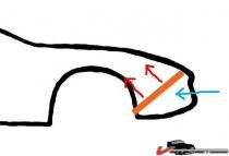
Then, a simple graphic showing the "go-zinta/go-zouta:"

thum_12694de3f75694cc8.jpg


Not a C3, but you get the idea for the hood vent:

thum_12694de3f766c6921.jpg


Must be a good idea - Looks like Greenwood used it too!

thum_12694de3f776db68b.jpg


An AIRBOX helps keep the flow Through the Radiator and Out the hood:
thum_12694de3f787244d6.jpg

Here's a nice shot showing the forward Laydown Radiator:
thum_12694de3f7977ea1c.jpg

Thats the approach I'm planning, enough typing - I have some work to do!

Cheers - Jim
 
Last edited:
thanks for the pics of the different arrangements. I've thought about making the hood shorter and have the forward edge at the top of the core support. That way I can lean the radiator forward and not have to worry about the hood hitting it when opened

I've opened the vents (heat extractor at the front) on the L88 hood back when I was having cooling issues. I may block them and see if the air flow changes in the future.

I need to spend some time sealing the front area with weather stripping to make sure all the air is passing through the radiator. I lost the top piece of weather stripping on the core support while driving a while back and could see a voltage drop on the meter when measuring voltage from the fan motor.

It will be interesting to see how big of a difference sealing the front will make on flow.

Right now I can look through the hood scoop and see daylight between the core support weather strip and the hood so I know I'm letting air around the radiator.

Neal
 
A few shots of the data I've got logged so far.

The gold line is the fan voltage and the black line is the motor rpm's, I'm runing 4:11 gears so just double the rpm for the mph. Its not perfect but its close. The mph are a little lower than the doubled rpm, 2500 is around 48 mph.

Starts producing voltage at about 40 mph, 3.5 volts at about 60 mph
P1010032.JPG
[/IMG]

Just under 60 mph 3 volts, right at 100 mph is 5 volts. this is the max my data logger will show/
P1010034.JPG
[/IMG]

cruising at 3000 rpm (60 mph) right at 3 volts, increase to 3500 rpm (70 mph) volts jump to 3.9 volts.
P1010133.JPG
[/IMG]

I punctured a tire sidewall (not sure how I did that) so it may be a little while before I can do some more testing.

I'll post back when I get some more data.

I don't have a screen snag program so I took pics with my camera and posted, that's why they are not very clear. You have to have the logging program to be able to view the file in its original format.

Neal :)
 
Last edited:

Latest posts

Back
Top