Need a crash course in crossfire.

enkeivette

Well-known member
Joined
Mar 30, 2008
Messages
990
So I'm installing Vettezuki's stock 82 crossfire engine in my jet boat. I was originally going to put on my edelbrock intake and carb and run it like that. But last night I got the idea to try and run it as is, with the crossfire/ computer.

So I have a few basic questions, feel free to include any info you think I might need.

First and foremost, does the 82 computer rely on an O2 sensor to meter the fuel? Or adjust the AFR? This is a water log exhaust so I would have to get very creative if I need an O2 sensor.

I'm missing the main wiring harness, the engine loom/ connectors are still there. Can I just get connectors for the computer and splice in the wires I need? Any diagrams out there for this?

Fuel pressure. I do have an electric pump in the boat, but I'm guessing it is very low psi since it goes directly to the carb without a regulator. What sort of psi will I need?

Finally, is this a smart computer that is going to freak out because I've ripped the smog equipment/ and probably some sensors off without realizing it. Is it going to want to run in limp mode all day or will it do ok stripped down with only the essentials?
 
I would change the intake. A well tuned carb with a well curved HEI would be SO much easier and reliable.
Yes, the oxy sensor runs the A/F
 
So I'm installing Vettezuki's stock 82 crossfire engine in my jet boat. I was originally going to put on my edelbrock intake and carb and run it like that. But last night I got the idea to try and run it as is, with the crossfire/ computer.

So I have a few basic questions, feel free to include any info you think I might need.

First and foremost, does the 82 computer rely on an O2 sensor to meter the fuel? Or adjust the AFR? This is a water log exhaust so I would have to get very creative if I need an O2 sensor.
Yes, crossfire is a closed loop EFI system, just like TBi & TPI, in fact it's a TBI system w/ 2 Ts and a parallel split wiring for the IAC. Nothing fancy or mysterious. I'm pretty sure you can get an O2 adapter for a boat manifold

I'm missing the main wiring harness, the engine loom/ connectors are still there. Can I just get connectors for the computer and splice in the wires I need? Any diagrams out there for this?

Get a later model TBI harness, all you need to do is add an intake temp senor 9simply drill lid and tap it)

Do a search, I think I posted the complete wiring diagram before. I don't have it here.

Fuel pressure. I do have an electric pump in the boat, but I'm guessing it is very low psi since it goes directly to the carb without a regulator. What sort
of psi will I need?

10-14 but a TPI pump is the best way to make sure you have plenty of flow, a new TBI pump is marginally adequate and once it wears it becomes an issue.

Finally, is this a smart computer that is going to freak out because I've ripped the smog equipment/ and probably some sensors off without realizing it. Is it going to want to run in limp mode all day or will it do ok stripped down with only the essentials?
[/quote]

it's not going to freak out, the smog crap is controlled, not monitored. It will run bare bones w/ just map, tps, cts, iac, o2, knock
 
Can't run any O2 sensor, the water manifolds preclude that, never reach temp and gets wet, no chance for it.....
even the later factory FI boats don't have one, use a earlier HEI ignition....

I did a FI conversion on a Volvo 4 cyl boat I had years ago, ran the Volvo FI rail with a GM Grand Am computer, made my own sending unit for it....kept the stock points dizzy....

one thing to watch out for is to use Aeroquip fuel hose, in order for fire protection to pass any inspection....:shocking:

the computer will be running in limp home mode as mine did, set ever code in the book, but MY boat got twice the fuel economy as the old carb did.....
besides picking up 3 prop sizes due to greatly increased power....the old prop just spun like crazy with the added power, took forever to get on plane, then the new cupped stainless prop made it act like a drag boat, snap your head back but good, on plane in a boat length....

:shocking:
 

They showing the upper housing like on a buddies boat, on his 350 chebby boat the water comes into the lower manifolds....then feeds to the uppers with the exhaust....I fail to see how that thing ever would reach 600f even if heated....Eric's boat is seawater cooled, no exchanger, standard water pump in front, fed by outdrive impeller....out the special stat housing to the mani's....

out that top piece to the outdrive water discharge....

that's all I know....
couple of years ago we had it apart a million times, so it seems...

:shocking:
 
That O2 sensor adapter is going to double to cost of my swap. I think I'm just going to try to port the water outlets into one exhaust manifold, leave one dry and drill and tap for the O2 sensor in that one. This way the water inlets will still run into each manifold, cooling it down the same, but after running through the motor, only shoot out on one side.

TT, you confused me about adding a temp sensor. If I'm using an 82 computer, an 82 crossfire setup, and a later year harness... why would I need to add anything?

So on my list of junkyard parts:
A TPI pump from... which year Camaros? Do I need a regulator?
A computer pigtail cutoff from... which year Camaros?

Anything else?
 
Last edited:
Knee deep in solder.

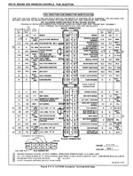
OK, so I think I know most of the wires I need to get this motor running. But I'm still lost on a few, I'm going to copy the ECM connector wiring diagram and put everything that I think I need in bold. If I'm wrong or I'm missing something, please chime in.

Also, I don't see the ground and I'm putting question marks by things that I think I might need, but don't know what they are.

Crank Discrete???
Dist Ref Hi???
Dist Ref Lo???
Coolant Temp
Throttle Pos Sensor
Third Gear
Load Temp Func 2
O2 Sensor Hi
Canister Purge/ Fan Control
HEI Bypass
+5V Return???
Stepper Coil B Hi???
Idle Air Control B Lo
AIR SW Sol
O2 Sensor Lo
AIR Divert Sol Out
Idle Air Control A Hi
Idle Air Control B Lo

HEI Spark Timing
Manifold Absolute Pressure
Manifold Temp
Load Temp Func

Scaling Res Lead B
Speed Sensor
(ALDL) Diag Conn In
Spark Retard Control
Park Neutral SW
Single Duel Inj. Sel.
Serial Data
Inj #1 Drive
Injector #2 Drive

+12 Batt
+5V Sens Ref. ???
Sys. Return ???
Sys. Return ???
Fuel Pump Relay Return
12V Battery
12V Ign Switch
12V Rly Switch ???
Fuel Pump Rly Drive
Torque Converter Clutch
Eng. Check Light
AC Clutch
Fourth Gear
Vehicle Elapsed Time
Scaling Resistor Lead A
 
OK, so I think I know most of the wires I need to get this motor running. But I'm still lost on a few, I'm going to copy the ECM connector wiring diagram and put everything that I think I need in bold. If I'm wrong or I'm missing something, please chime in.

Also, I don't see the ground and I'm putting question marks by things that I think I might need, but don't know what they are.

Crank Discrete??? dunno that one
Dist Ref Hi???
Dist Ref Lo??? If you want computer to run ign timing, you will need 4 wires to the dizzy....one is a ground to the computer 3 are signal wires, one of which was a tan/bk tracer to pull for timing adj on a TPI anyway....
Coolant Temp yes, needed
Throttle Pos Sensor yes, 3 wires, one is +5 one is sensor output, other is ground at the computer....as are maybe 3? other wires on the sensor setup, you can NOT ground directly to the engine, you need take that signal wire back to the computer so it sees a clean signal, without that injector pulse riding on any ground leads, messing up the smooth signal....
Third Gear tell it that it's always in 3rd gear....I don't remember any such signal...but it's been a while.....
Load Temp Func 2 ??
O2 Sensor Hi
Canister Purge/ Fan Control eliminate
HEI Bypass isn't that the tan/black timing wire...??
+5V Return??? sounds like the +5 ground at the computer mentioned above....
Stepper Coil B Hi???
Idle Air Control B Lo
AIR SW Sol I dunno what that is......
O2 Sensor Lo sometimes they had a signal wire going back to the computer to ground the O2 sensor signal, I still doubt you going to get one in there....it will run without closed loop....
AIR Divert Sol Out
Idle Air Control A Hi
Idle Air Control B Lo
You should have the same 4 wires running two IAC motors, in parallel as I had for the single motor on the TPI setup.....
HEI Spark Timing
Manifold Absolute Pressure +5 volts, signal and grounded at computer.....
Manifold Temp sounds like incoming air temp...two wires I think, ....one is ground at the computer, other is signal...all that and the coolent temp sensor ARE is a variable resistor for temp....gets their operating bias from the computer, so only 2 wires needed for each.....

Load Temp Func ??

Scaling Res Lead B ??
Speed Sensor obviously nothing, disconnected.....
(ALDL) Diag Conn In
Spark Retard Control
Park Neutral SW set for in neutral
Single Duel Inj. Sel. tell computer there are 2 injectors....
Serial Data
Inj #1 Drive
Injector #2 Drive
On a TPI, the injector banks are grounded at the engine, along with power grounds from the computer, which is why signal wires have their own +5 volt grounds at the computer, NOT the engine...
+12 Batt that is main power to computer, maybe have 2-3 inputs for it....one is computer memory, other is injector power and a 3rd runs the 5 volt line regulator on the computer board.....
+5V Sens Ref. ??? that is the +5 to the TPS and MAP.....
Sys. Return ???
Sys. Return ??? those are ground wires back to the computer
Fuel Pump Relay Return sounds like for the relay coil, ground?? either way those are wired, the computer tells the relay to close and start the pump....
12V Battery
12V Ign Switch
12V Rly Switch ??? discussed above
Fuel Pump Rly Drive sounds like the coil of the FP relay is grounded on one end and the computer puts 12 to the coil?? could be the coil is ignition hot, and maybe computer grounds the other end to close relay, I forget.....sorry.....
Torque Converter Clutch eliminate
Eng. Check Light eliminate, as it will always be 'on'....
AC Clutch eliminate
Fourth Gear eliminate
Vehicle Elapsed Time eliminate
Scaling Resistor Lead A
??? dunno what that is....

have fun....:flash:
 
Crank Discrete??? you need this cranking discrete or it won't start.
Dist Ref Hi??? distributor reference signal, need it too
Dist Ref Lo??? yup need this
Coolant Temp coolant reading, cts sensor in front of manifold, very important. won't run without
Throttle Pos Sensor
Third Gear third gear discrete,
Load Temp Func 2
O2 Sensor Hi
Canister Purge/ Fan Control
HEI Bypass needed, it's the hei signal to the ecm and disconnected to set timing
+5V Return??? sensor reference 5V needed
Stepper Coil B Hi??? IAC motor control, needed. There should be 4, 2 highs and 2 lows. This is how a stepper motor is controlled, with 4 pinouts. All these are needed. The 2 iacs are wired parallel.
Idle Air Control B Lo
AIR SW Sol not needed
O2 Sensor Lo
AIR Divert Sol Out not needed
Idle Air Control A Hi
Idle Air Control B Lo

HEI Spark Timing needed, this is the EST control signal.
Manifold Absolute Pressure
Manifold Temp
Load Temp Func

Scaling Res Lead B
Speed Sensor better if you used it
(ALDL) Diag Conn In needed or you will never be able to diagnose.
Spark Retard Control
Park Neutral SW needed for cranking
Single Duel Inj. Sel.
Serial Data
Inj #1 Drive
Injector #2 Drive

+12 Batt
+5V Sens Ref. ??? 5v voltage reference needed
Sys. Return ??? ground needed
Fuel Pump Relay Return needed
12V Battery
12V Ign Switch
12V Rly Switch ???
Fuel Pump Rly Drive
Torque Converter Clutch
Eng. Check Light needed for diagnosing
AC Clutch
Fourth Gear
Vehicle Elapsed Time needed, this is the gold box that i included. The E cell timer. It's used to count down when the engine was new, it's a bit of an obscure part but most likely for fuel and timing modifiers when the engine was new. Anyway, don't cut it off. Could lead to weird issues.
Scaling Resistor Lead A

This is the actual connector
2482f3ff62b6cc.gif

Of all these only the canister purge, the air divert, air switch sol., AC clutch can be left out;. The VSS too but I would advise to use a dummy signal or simply hook it up to a trans mission output since this signal is used to reset IACs and other stuff above a certain speed (I think it was 16mph)
 
Thanks guys. As always TT you are a life saver.


You wrote third gear discrete, does that mean I need that one?

Since the motor is hooked to a jet drive, I think I'm SOL on the speed sensor and what should I do about the Park Neutral? Just hook it up to 12V?

I missed a lot... Was I right on with what I had in bold at least?
 
I'm confused by the wiring diagram from the injectors to the ECM, but I traced the wires from the HEI to the ECM, and these connectors do not go together.


14kv08y.jpg
 
I'm confused by the wiring diagram from the injectors to the ECM, but I traced the wires from the HEI to the ECM, and these connectors do not go together.


14kv08y.jpg

GM changed the connector for the distributor a couple times. That connector looks like it would be for the 86 style screw down distributor cap style.

Aren't boat run in open loop anyways when EFI is used?
 
Injector Wiring

Ok, I circled what confuses me in red in this wiring diagram.

The injector drive wires from the ECM terminate into these small ovals before reaching the injectors, then the wires change color. Do the ovals just show the wiring is crimped to another color wire? Or are they resistors or something???

Second, the return from the injectors goes to this pink wire that also feeds to the distributor and to the neutral safety switch and something else "GA" and "DIR B.U." What is this wire? What should I hook it up to?

:surrender::confused2::confused:

153p445.jpg
 
Adam,
The two ovals that you circled ARE the injectors.

Dir B/U is the back up lamps.

The pink "maybe" a keyed hot. Cannot tell without page 2 of the schematic.
 
That's what I thought at first too, but the injectors are on page 2. I'll post it in a min.
 

Latest posts

Back
Top