Holley's schematics include some mistakes also. Just to keep it interesting.
You are using an out of date browser. It may not display this or other websites correctly.
You should upgrade or use an alternative browser.
You should upgrade or use an alternative browser.
Plastic Fantastic 2
- Thread starter SuperBuickGuy
- Start date
SuperBuickGuy
Well-known member
grand, can't wait to find them.... Merry Christmas to all (except Holley)Holley's schematics include some mistakes also. Just to keep it interesting.
did I mention that they've sent me a second programmer and it doesn't work either?
SuperBuickGuy
Well-known member
Sensors work, fuel line leaks (well, after I swapped the lines)
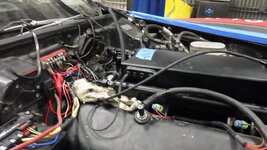
remove sensor for now
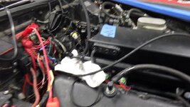
start on accessories
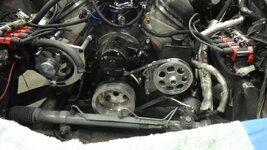
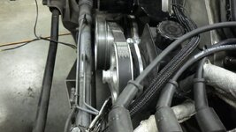
It does pop.... which means I have spark and fuel, just not at the right time. Add to this that I zero lashed the rockers - and I have a couple steps before it truly makes sweet noise (like putting a cooling system together and making the accessories work).
I have questions about spark control... and I need to spend some quality time understanding what I need to do.... but still, it will run.
Merry Christmas

remove sensor for now

start on accessories


It does pop.... which means I have spark and fuel, just not at the right time. Add to this that I zero lashed the rockers - and I have a couple steps before it truly makes sweet noise (like putting a cooling system together and making the accessories work).
I have questions about spark control... and I need to spend some quality time understanding what I need to do.... but still, it will run.
Merry Christmas
phantomjock
Well-known member
I'm late - so; hope you had a Merry Christmas! Also - plan on having a Happy New Year!
Cheers - Jim
Cheers - Jim
SuperBuickGuy
Well-known member
My ADD on full display
Langmuir cnc plasma
I bought this years ago (2015 ish) never really used it because I rarely copy parts.... and it is kind of time consuming for one-offs. With that said, it also didn't have a Z-axis control - which leads to a challenge getting parts to look good as the plasma varies in height over the material. ... my wife has some parts that need to be cut out, so it was a good 'excuse' to get it updated.... so here we go.....
mostly it's been a computer stand
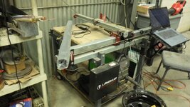
out with the old
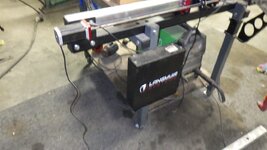
but given how 'old' it is, they sent an entire, new computer... which also means I have an x/y axis control (read mill) that is now homeless
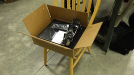
as with anything else, break every warranty... this time, the Z-axis parts need to be installed in the new controller
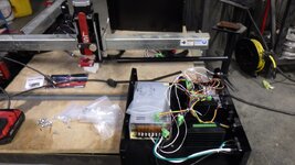
as an aside, it's amazing how close I got to making one from scratch.... all the parts inside I know and know what they do....
you can tell that it's replaced because it's less dusty
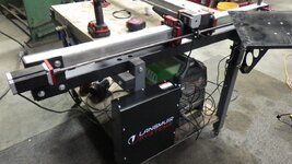
need to run it in, but ready to go
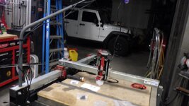
Langmuir cnc plasma
I bought this years ago (2015 ish) never really used it because I rarely copy parts.... and it is kind of time consuming for one-offs. With that said, it also didn't have a Z-axis control - which leads to a challenge getting parts to look good as the plasma varies in height over the material. ... my wife has some parts that need to be cut out, so it was a good 'excuse' to get it updated.... so here we go.....
mostly it's been a computer stand

out with the old

but given how 'old' it is, they sent an entire, new computer... which also means I have an x/y axis control (read mill) that is now homeless

as with anything else, break every warranty... this time, the Z-axis parts need to be installed in the new controller

as an aside, it's amazing how close I got to making one from scratch.... all the parts inside I know and know what they do....
you can tell that it's replaced because it's less dusty

need to run it in, but ready to go

SuperBuickGuy
Well-known member
it does start-ish... timing is way late, but the good news is fuel and spark IS happening - so now it's just a matter of fine tuning.... oh, and I didn't send the intake into low earth orbit.... so win, win
also got the belts lined up
3/8" spacers
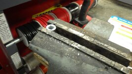
installed
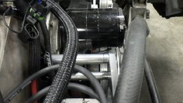
and here it is
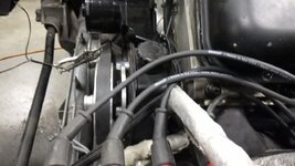
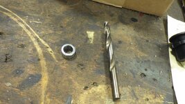
had to drill out the power steering spacers - still not thrilled with how wobbly it is - if it's noisy, I'll have to make a bracket
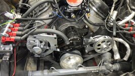
also got the belts lined up
3/8" spacers

installed

and here it is

had to drill out the power steering spacers - still not thrilled with how wobbly it is - if it's noisy, I'll have to make a bracket

SuperBuickGuy
Well-known member
finished the belts.... even got the right belts the first time...
then made a hole
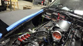
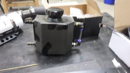
to replace the leaky reservoir
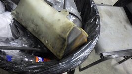
with one that doesn't leak
in other news, for the first time in my existence I had a truck come through with too small of a carb.
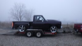
backstory, guy on a neighbors page was having trouble with his 406 sbc. wouldn't run over 3000 rpm and running extremely rich..... well, if you put a 650 carb on a motor that needs 700 cfm minimum, it'll pull fuel in its search for air. Loaned him an 870 that I had on the Buick.... thing runs hard... he's quite pleased, figured I better get at least one good deed in in 2023.... beautiful truck, it's purple.
and the Corvette. It's popping like it wants to start - but not triggering my timing light - which suggests it's just fuel detonating with compression... so much of the rest of my day has been doing a deep dive on what I need to do to make it roar. but alas, I'm always breaking trail - and this is no different.

then made a hole

to replace the leaky reservoir

with one that doesn't leak

in other news, for the first time in my existence I had a truck come through with too small of a carb.

backstory, guy on a neighbors page was having trouble with his 406 sbc. wouldn't run over 3000 rpm and running extremely rich..... well, if you put a 650 carb on a motor that needs 700 cfm minimum, it'll pull fuel in its search for air. Loaned him an 870 that I had on the Buick.... thing runs hard... he's quite pleased, figured I better get at least one good deed in in 2023.... beautiful truck, it's purple.
and the Corvette. It's popping like it wants to start - but not triggering my timing light - which suggests it's just fuel detonating with compression... so much of the rest of my day has been doing a deep dive on what I need to do to make it roar. but alas, I'm always breaking trail - and this is no different.
SuperBuickGuy
Well-known member
this is supposed to be in the help? area of the software.... it's not working, so here it is for me to reference tomorrow...
ah winning... instructions for tomorrow...
1.0 CRANK SENSOR SETUP
1.1 Ignition Reference Setup – "one pulse per fire" trigger, Magnetic Pickup
The following shows how to setup the crank signal for a "one pulse per fire" RPM input using either a Magnetic pickup crank trigger or distributor.
A "one pulse per fire" trigger means there is one sensor pulse for every cylinder firing (on a V8 this would be a 4 pulse crank trigger or a 8 pulse trigger in the distributor).
NOTE: In the software, the Sensor Type should be setup as "Magnetic".
1. Note the Ignition Reference Angle set in the software. This is typically set to a value that is 10° more than the highest timing you will run.
Do NOT set it higher than 75°. 60° is a common value. 60° is used for an example here.
2. Turn the engine over so that it is at the Ignition Reference Angle. For this example it would be 60° BTDC on cylinder # 1
The timing pointer should be indicating 60° BTDC on the crank.
3. Align/turn the crank trigger or distributor so that the sensor is perfectly inline with the trigger.
• For a Magnetic pickup crank trigger, this means the pickup and a magnet should be inline.
• For a Magnetic pickup distributor, this means having one of the reluctor teeth line up with the Magnetic pickup.
4. Tighten every thing up.
5. If you are not using a cam sync (if you are, continue to section 2.1), everything should be set close enough to start the engine.
It is recommended that you disconnect the injectors and crank the engine over.
Look at the timing with a timing light. It should be firing at the cranking timing value shown on the data monitor.
If it is off a few degrees, you can move the pickup slightly, or change the Ignition Reference setting to sync things up.
If you change the Ignition Reference value, note that you must cycle the ignition power for it to take affect.
and
2.1 Cam Sync setup when using a "one pulse per fire" crank input
For a "one pulse per fire crank" signal (e.g. a 4 pulse crank trigger on a V8), the cam sync signal must occur in a specific range to properly identify which cylinder is cylinder # 1 If this is not done properly, individual cylinder trims will not be performed on the correct cylinder, or worse, if using individual coils, the wrong cylinder will be fired, potentially damaging the started, flexplate, or worse.
The best way to determine the proper range is by using the following basic formula to determine the crank angle range that the cam identity can occur. An example is give afterwards along with a table that has certain combinations already calculated.
Cam sync location (degrees BTDC #1) = "Ignition Reference Angle" + "A" + ("A" / 2)
"Ignition Reference Angle" = Taken from Crank Sensor Setup in software
"A" = Angle Between Crank Pulses (crank degrees between triggers on the crank sensor)
"A" for a 8 cylinder = 90°
"A" for a 6 cylinder = 120°
"A" for a 4 cylinder = 180°
Using the formula above, plug in the "Ignition Reference Angle" you are using and the proper "A" value depending on the number of engine cylinders.
The location calculated is the "ideal" location and can vary +/- 30° or possibly more.
If you are out of this range contact Holley Tech Service for options.
Example - 8 cylinder with a Ignition Reference Angle of 60°
Cam Sync Location = 60 + 90 + 90/2 = 195 degrees BTDC #1
Cam Sync Location = 60 + 90 + 45 = 195 degrees BTDC # 1
195° would be the centrally "perfect" location for this specific example.
However, this location can vary by +/- 30 degrees from this nominal target value with no issue.
Number of Cylinders Ignition Reference Angle Cam Trigger Location Range (BTDC #1)
4 60 330 +/-30 degrees
6 60 240 +/-30 degrees
8 60 195 +/-30 degrees
SuperBuickGuy
Well-known member
It runs... that math for the cam sync? utter and complete BS. It DOES need to be set in advance of the crank signal - and Holley recommends at least 10 degrees - but that 195 degree stuff. nope.
phantomjock
Well-known member
Or is this Premature Ignition?
Cheers - Jim
SuperBuickGuy
Well-known member
or vaporware? get it? fuel injection, vapor
Or is this Premature Ignition?
Cheers - Jim
SuperBuickGuy
Well-known member
yes it now runs - which is pretty amazing... and one more step closer to building the 50 Buick....
the problem.... the magnetic pickup doesn't have enough adjustment to get 60 degrees of BTDC advance - so I moved it to the other side and mounted it inside the power steering bracket.... worked really well other then being really fiddly trying to hold everything in place. It was nice having Rory here to help (the guy who owns the truck I posted a picture of yesterday)
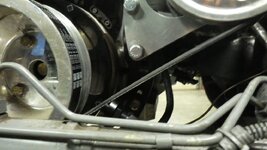
the next thing - cap the holes I made when I removed the cross bar
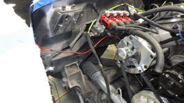
cap 2
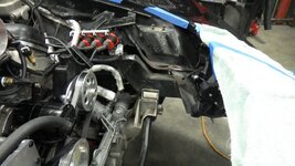
with the success of getting it running, time to put a cooling system back in place....looks like I'll be doing some warranty voiding real soon
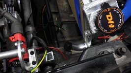
to avoid confusion, I have 2 C3 Corvette radiators, this one got damaged in the move so it's become the test dummy
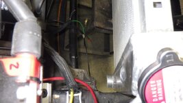
as we all know, boxes are great radiator mounts
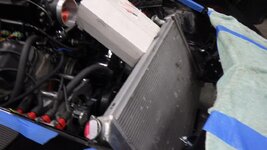
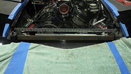
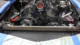
cut the radiator support... was utterly full of rust.... so beside modification, there will be some repair. this will allow the intake air to come over the radiator
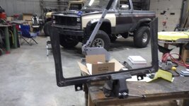
before cutting
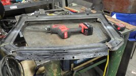
also removed the bottom support so I can slide the radiator down an inch or so
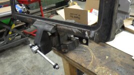
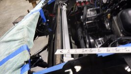
need to check the fans to make sure I have clearance for them
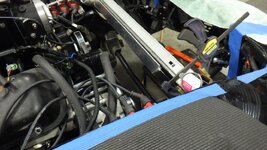
back to test fitting
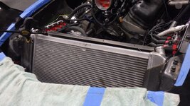
with the top bar cut off, I can lower the radiator I may put holes in the bottom to help with airflow
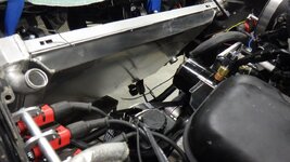
keep also in mind that the way the hood opens leaves precious little space from the stock location
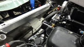
the problem.... the magnetic pickup doesn't have enough adjustment to get 60 degrees of BTDC advance - so I moved it to the other side and mounted it inside the power steering bracket.... worked really well other then being really fiddly trying to hold everything in place. It was nice having Rory here to help (the guy who owns the truck I posted a picture of yesterday)

the next thing - cap the holes I made when I removed the cross bar

cap 2

with the success of getting it running, time to put a cooling system back in place....looks like I'll be doing some warranty voiding real soon

to avoid confusion, I have 2 C3 Corvette radiators, this one got damaged in the move so it's become the test dummy

as we all know, boxes are great radiator mounts

cut the radiator support... was utterly full of rust.... so beside modification, there will be some repair. this will allow the intake air to come over the radiator

before cutting

also removed the bottom support so I can slide the radiator down an inch or so

need to check the fans to make sure I have clearance for them

back to test fitting

with the top bar cut off, I can lower the radiator I may put holes in the bottom to help with airflow

keep also in mind that the way the hood opens leaves precious little space from the stock location

SuperBuickGuy
Well-known member
time will tell whether or not my hood gets all pins.... my air filter plan is something similar to a C5 Z06... I have a great deal of work to do on the structure because I need to have a tow point on the front bumper and there isn't solid enough structure there now for thatI know what your saying about the open hood is basically a small gap between the underside of the hood and the radiator. No room for a filter.
I haven't worked on this for a while but I did try moving the hinge pivot forward to increase the gap.
View attachment 56321
SuperBuickGuy
Well-known member
90% prep, 10% work.... tonight I got started by cutting down a knife die to use in my press. For those curious, I have FAR more money in dies then I do press....
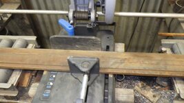
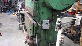
knife die is a die that will bend 135*... this is the bottom of the die I cut
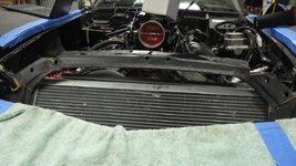
so here's a visual of why I'm doing this.... I now have 4" above the radiator to run the intake. The old piece is on
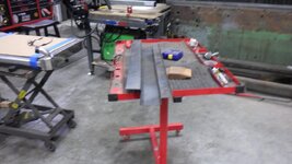
what came out of the bending process - it'd be nice to have a CNC, hydraulic brake but for now I have a BFH
after cutting and bending and pounding
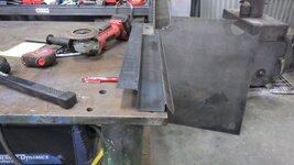
lots of fitting... here, I made a mistake, I should have flattened the knife brakes before I bent the 90* front bend.... now it won't go into the brake
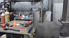
before I made the shroud fit
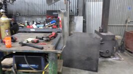
test fit
where I finished.... lots more to do such as blow holes to allow air into the bottom of the radiator

knife die is a die that will bend 135*... this is the bottom of the die I cut

so here's a visual of why I'm doing this.... I now have 4" above the radiator to run the intake. The old piece is on

what came out of the bending process - it'd be nice to have a CNC, hydraulic brake but for now I have a BFH

after cutting and bending and pounding

lots of fitting... here, I made a mistake, I should have flattened the knife brakes before I bent the 90* front bend.... now it won't go into the brake

before I made the shroud fit

test fit

where I finished.... lots more to do such as blow holes to allow air into the bottom of the radiator

SuperBuickGuy
Well-known member
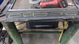
and carrying on - laying out the top
what was destined to be handrail is now a corvette part
side view
the part I made yesterday needs some air holes
drill holes....
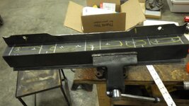
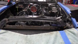
this is where I stopped tonight - trying to picture what the top will look like. This piece is so chopped up and damaged that it's not going back on....
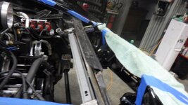

what was destined to be handrail is now a corvette part

side view

the part I made yesterday needs some air holes

drill holes....

this is where I stopped tonight - trying to picture what the top will look like. This piece is so chopped up and damaged that it's not going back on....


SuperBuickGuy
Well-known member
more radiator - tonight's episode, tetris
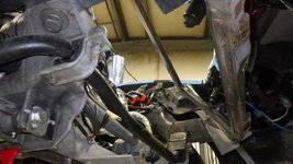
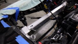
started with the real radiator and was pleasantly surprised that it's a bit narrower... still won't go in through the top
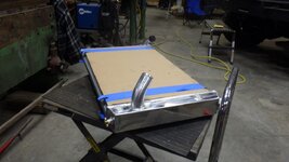
well, it will if you rotate the bottom of the core support
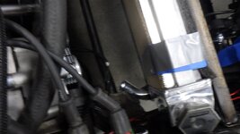
then the right answer is 'void every warranty'
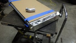
taped the outlet to the radiator to test fit
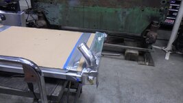
and finally, it worked.... I pity the fool who owns this next and tries to remove the radiator....
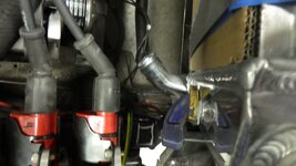
it's so tight that you have to choose your radiator cap carefully
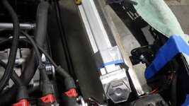
but it all fits.
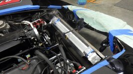
why did I cut it? the outlet is at the very bottom of the radiator (which opens up another set of issues)
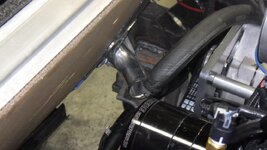
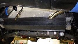
beside the creative hosework that's coming, it also is over the transmission cooler.... to be honest, I don't know what the Chinese were thinking... the cooler takes up at least 2/3rds of the available space - which, on a car that already has cooling issues... isn't a good idea
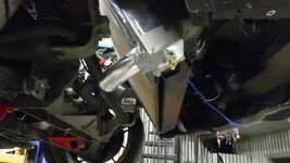
That leads me to what's next.
but onto the next problem... notice how much further the motor outlet is compared to the radiator?
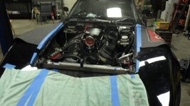
I need to get a remote, pressurized reservoir. I'll probably just leave the cap in place. With that said, I need to get the tube out of the side tank. I also have to put a heater return line into the radiator. This is good because that's the line I'll tap for the reservoir.
Ah the joys of hotrodding

started with the real radiator and was pleasantly surprised that it's a bit narrower... still won't go in through the top

well, it will if you rotate the bottom of the core support

then the right answer is 'void every warranty'

taped the outlet to the radiator to test fit

and finally, it worked.... I pity the fool who owns this next and tries to remove the radiator....

it's so tight that you have to choose your radiator cap carefully

but it all fits.

why did I cut it? the outlet is at the very bottom of the radiator (which opens up another set of issues)

beside the creative hosework that's coming, it also is over the transmission cooler.... to be honest, I don't know what the Chinese were thinking... the cooler takes up at least 2/3rds of the available space - which, on a car that already has cooling issues... isn't a good idea

That leads me to what's next.
but onto the next problem... notice how much further the motor outlet is compared to the radiator?

I need to get a remote, pressurized reservoir. I'll probably just leave the cap in place. With that said, I need to get the tube out of the side tank. I also have to put a heater return line into the radiator. This is good because that's the line I'll tap for the reservoir.
Ah the joys of hotrodding
SuperBuickGuy
Well-known member
I caved, I signed up for Optima Challenge in Portland .... I have until July to get this done... but realistically, early May so I can run a few Autox events
mfain
Well-known member
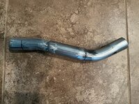
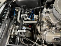
Looking good. I'm glad you signed up for Optima. I had the same issue with the lower radiator hose. I ended up mocking up a connector to fit the limited space (1st photo) and sent that to Brown and Miller (BMRS) to bend up in aluminum with beads added at the ends. Then I used a 45* silicon coupling hose from the radiator outlet to the connecting tube at one end ("1" in the second photo) and a 90* silicone elbow at the other end (3) to connect to the water pump.
