rack and pinion question

can you give me the link ? And maybe a parts list ?

If my eyes are not deceiving me it looks as if the link is awfully close to the headers, almost touching.

Can I assume that the R&P makes the car steer like a modern car ? I'm used to European cars steering systems and never seem to get used to the vettes steering box.

Get hold of TT here, Marck knows the numbers, and the European cars that have that same rack.....too many years now, so I forget what TT said, but there was a fellow named Yoshi??/similar name from northern Europe who did a conversion, and so it was eventually traced to the CTO rack same as the '89 Grand Am my rack came from, and YES there is NO comparison between the rack at 2.7 turns L-L vs the sloppy stock set up that steered like a bus.....but of course a smaller wheel, wide tires on 17" rims, revamped suspension Bilstein sport shocks, and a rear plastic spring make all the difference in the WORLD, with every change over the early years of my ownership of this '72, bought it in '95.....the improvements were amazing....and I would not know Jack Squat about doing these improvements without the internet and talking/typing/meeting with other guys of similar asspirations for their cars.....

:lol:
 
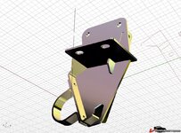
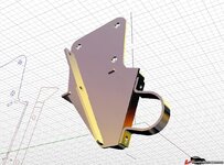
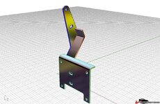
My R&P post is http://www.vettemod.com/forum/showthread.php?t=4338 with pictures.

I also commented with some additional pictures in Karstens (MYBAD79) R&P post.

The Saginaw CTO (Center Take Off) R&P we use is from mid 90s GM FWD midsize cars ( Pontiac Grand Am ect) . You will find the same type steering box in a mid 90s SAAB 900 (A/C 19320502). Typical source here is Rockauto. Note these GM steering boxes suffer from "morning sickness" where they don't work well when started after they have been in service for a lot of miles so a rebuilt unit is suggested.

GM built many different P/N units with identical exterior dimensions and steering ratios and amount of travel. The amount of steering effort is controlled by the diameter of an internal torsion bar which is not serviceable. The rebuilders do not seem to differentiate these nuances and basically lump all power units as quick ratio (2.5 turns) or standard(2.75 turns). So your steering feel will be to some extent down to luck.

You can find the u-joints and shafts in either the Flaming River or Bergson catalogs. The part numbers for joints/shaft vary depending on your material choice and shaft diameter and connection choice (double D or splined). If you use an 3 u-joint intermediate shaft design so you do not collapse the steering column you will need a support bearing which can be sourced from Summit. I can't find the P/N for the GM mounting bushings and clamps for the R&P assembly but I sourced them locally from the dealer.

You are correct in your observation that I don't have a lot of clearance at the #1 header tube. The old chrome headers cleared much better but the new stainless ones are very tight and have been "dimpled" for clearance. Surprise - both headers are Hookers just 30 years apart. I have not cooked the u-joint yet.

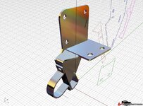
All the mounting brackets, center bracket, tie rods, power steering hoses are custom made. I think MYBAD79 has documented these most comprehensively.

Grampy
 
From the daze of having the stock steering and the '89 vette wheels on the car with 255/50 rubber on front, I had to limit the steering throw to keep tires from rubbing on swaybars/frame so added a bolt to the lower A arms to hold the snubbers off a tad.....

and noted the 2.7 turns R/L on the wheel is infinately quicker than stock, but in fact I have NO clue about the actual throw/turns of the rack itself.....

:bonkers::shocking:
 
Sort of on-topic, I was watching the latest episode of Fantomworks last night, and they were fixing a bastardized resto-mod of a '53 Mercury wagon that a previous shop had left unfinished. One thing that the other shop had tried to do was use a steering rack with tie rods that were far longer than the car's control arms. Kind of interesting to see a general audience show talk about bump steer, but they never did say what they did to solve the problem.
 
For sure my friend. Do you have a 3D design programm like SolidWorks or something similar? In that case, you can have step-files or whatever you want.

Günther
 
Sam -
There are 3D viewers online you could use. Google will get you there. Plus, if you have a CNC machinist, they could do the milling for you too.

Cheers - Jim
 
Back with this subject.

It took me some time, but I finally found a suitable Grand Am power assisted steering rack out of a 1995 with only 80.000 miles on her.
Thanks again for the offer Karsten, but in view of shipping, taxes, this is just way easier. :beer:

Anyway, have been reading through the different threads and have a couple of questions left :

I understood that the tie rods being of equal length is a must. This means that the rack will be off center.

What about the height of the rack and the height of the tie rods ? I read that it affects bump steer, but what height does it need ?

Thanks
 
I used the same style on mine but I purchased new parts except the clamps. I have bump steer issues. the unit sits high enough and I really thought this worked out but pending on what the outcome I may just change to the borgeson system.

Gunther, can you email me the same documents?
[email protected]
 
Back with this subject.

It took me some time, but I finally found a suitable Grand Am power assisted steering rack out of a 1995 with only 80.000 miles on her.
Thanks again for the offer Karsten, but in view of shipping, taxes, this is just way easier. :beer:

Anyway, have been reading through the different threads and have a couple of questions left :

I understood that the tie rods being of equal length is a must. This means that the rack will be off center.

What about the height of the rack and the height of the tie rods ? I read that it affects bump steer, but what height does it need ?

Thanks
I am right in the middle of doing this and here are a couple of observations:

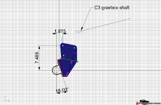
The rack is off center and that is not a big deal. What concerns me about most of these conversions is that the two bolts (on the rack) that serve as the tie rod bracket mounts are not in line with the tie rod mounts (axially). The tie rods exert a torque on the rack mount. Ideally, you would like to have the tie rods axially intersect the mount bolts on the rack. But this will give you geometrically lousy bump steer.

The you can minimize this by rotating the rack so that the two bolts are rotated up to get them closer to the tie rod axis. I have found that 18 degrees is optimal. The picture below will show the position of the rack for a BB car (with oil pan clearance).

Also, use the Grand Am bolts. They have a shoulder on them that counters the twist on the bracket.

As far as the steering shaft goes, use a double cardan joint at the steering shaft. This keeps the angles at less than 15 degrees. Using angles greater than this is a very bad thing.

4587248a650d60.jpg

4587248a78490d.jpg

4587248a6bac8c.jpg

4587248a7226d4.jpg

4587248a7e960c.jpg
 
I was thinking about the following things related to bump steer (please correct me if I'm wrong) :
- I think longer rods mean a greate length change when the tie rods go up and down during suspension movement.
- I would think you would want to have the rods horizontal when the suspension is at normal ride height, so that length changes are minimal during up and down movement of the suspension. However it might be that this is not possible.
- I also use the outer hole on the steering knuckle. Maybe it's better to use the inner hole and reduce the ratio somewhat since the power assisted R&P already has a short ratio. This would mean that the length changes of the tie rods have less effect on the steering knuckle.

As for the angle of the steering rack. I think space in the car and the connection with the steering column dictate what you can do

I would think that the steering rack bolts and center link need to be at the location where the original center link is.

PS : would you have those drawings in cad or any other technical format ?
 
I would think you would want to have the rods horizontal when the suspension is at normal ride height, so that length changes are minimal during up and down movement of the suspension. Think about it, as a general rule is you want the tie rod to make a parallelogram with the lower control arm.

I also use the outer hole on the steering knuckle. Maybe it's better to use the inner hole and reduce the ratio somewhat since the power assisted R&P already has a short ratio. This would mean that the length changes of the tie rods have less effect on the steering knuckle. The difference between the lateral position of the inner and outer hole is very small.

As for the angle of the steering rack. I think space in the car and the connection with the steering column dictate what you can do. You can put the rack wherever you want. I am talking about optimizing the rotation of the rack input to use a properly designed input shaft (with proper angles).

I would think that the steering rack bolts and center link need to be at the location where the original center link is. if the steering rack bolts are rotated up (to be at the location of the original center link) you will have a steering input angle that is unworkable.
 
Winter 01-02 someone told me BBShark?? to raise the center link and so I raised it by cutting the machine shop made link adapter and getting my welder buddy to weld the two output parts to a much higher position on the final assy.....that is of course where the stock tie rod ends go.....and the center link is same height as lower arm pivot now....

bump stear is a lot better than stock even AS I RECALL the right tie rod is 21" long and the left is 19" long......not so very far from the length as the Pontiac it came off of......:drink:
 

Latest posts

Back
Top