You are using an out of date browser. It may not display this or other websites correctly.
You should upgrade or use an alternative browser.
You should upgrade or use an alternative browser.
1958 MGA Coupe
- Thread starter bobs77vet
- Start date
GoVetteGo
Well-known member
Great work Bob - on the car and making tools!!!!
I don't know how you do it!! You are so meticulous with taking pictures. I go out to the garage, jump into something and AFTER i am done - SCHMIDT, I didn't take any pictures!! Wholly Moly!!! I'll have to hire a professional photographer just to keep up with the Bob's!!!
Oh, And I do enjoy your pictures!!
John
bobs77vet
Well-known member
thks John most of the photos are from my Blackberry phone and its so easy to have next to me it makes taking the pictures way too easy...
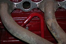
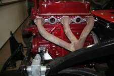
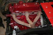
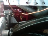
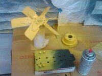
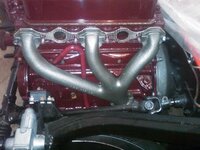
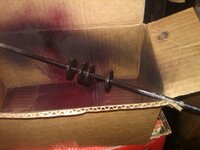
mostly I have just been cleaning up in the garage and taking care of loose ends until the correct timing chain cover seal arrives then i can finish the engine bolt ons.....in the last week i have painted the exhaust manifold, touched up fan and pulley, painted manifold washers and made a bracket to hold the tappet vent tube. there is a copper small P clip on the fuel pump blanking plate and i am wondering if there should be two of these for the gas overflow tubing of if the over flow tubes fit into just this one???
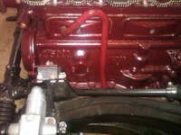
this is the copper P clip....i dont think there is any electrics over here and it makes me think this is for one of the carb overflow tubes do I need 2 of these ? do they both fit in this one P clip or are they connected with a "T" into one overflow tube?


mostly I have just been cleaning up in the garage and taking care of loose ends until the correct timing chain cover seal arrives then i can finish the engine bolt ons.....in the last week i have painted the exhaust manifold, touched up fan and pulley, painted manifold washers and made a bracket to hold the tappet vent tube. there is a copper small P clip on the fuel pump blanking plate and i am wondering if there should be two of these for the gas overflow tubing of if the over flow tubes fit into just this one???


this is the copper P clip....i dont think there is any electrics over here and it makes me think this is for one of the carb overflow tubes do I need 2 of these ? do they both fit in this one P clip or are they connected with a "T" into one overflow tube?


bobs77vet
Well-known member
denpo
Carburated Nihilist
Copper line??
bobs77vet
Well-known member
bobs77vet
Well-known member
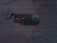
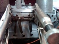
time to make some bracketry for the exhaust and the choke. the original MGA choke cable runs over the valve cover, since this is a carburetor for an MGB the choke cabling comes up from the bottom. the Mrs pointed out that there were lots of packages coming and getting smuggled out to the garage so i better start making my own stuff when i can.....
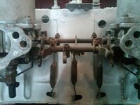
heres the basic set up and the front shaft is the choke

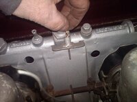
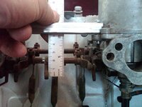
i measure the diameter of the existing accelerator cable abutment for reference
heres the idea. to span the distance using 1/2" square tubing and have the ends sit on a flange that has a hole on it and then drill the square tubing so it can be attached to the flange with the hole in it. the original design uses a bracket off of the front carb so i think its plenty strong for this application.

using an original style cable stop
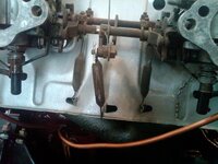
full closed choke
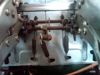
full open choke 1" pull
easy 3/16" cable abutment

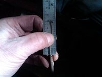
2" of cable required with the way i have it set up. i could rotate the cable stop bracket up some if i wanted to
and 2" of cable left on origninal cable. i may need to cut back the cabling 1/4" or so>
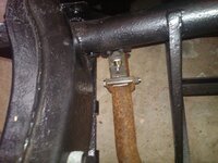
exhaust bracket
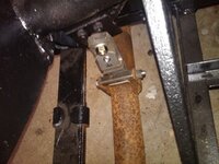
heres the basic set up and the front shaft is the choke


i measure the diameter of the existing accelerator cable abutment for reference

heres the idea. to span the distance using 1/2" square tubing and have the ends sit on a flange that has a hole on it and then drill the square tubing so it can be attached to the flange with the hole in it. the original design uses a bracket off of the front carb so i think its plenty strong for this application.

using an original style cable stop

full closed choke

full open choke 1" pull

easy 3/16" cable abutment

2" of cable required with the way i have it set up. i could rotate the cable stop bracket up some if i wanted to

and 2" of cable left on origninal cable. i may need to cut back the cabling 1/4" or so>

exhaust bracket


Last edited:
JPhil
Huh?
Actual choke or enrichener? How would that work on an SU?
I don't remember about the SUs on my big Healy 40+ years ago, but the SUs I ran on my Harleys had an enrichener which lifted the needle instead (I believe--that was 25-30 years ago too).
I don't remember about the SUs on my big Healy 40+ years ago, but the SUs I ran on my Harleys had an enrichener which lifted the needle instead (I believe--that was 25-30 years ago too).
bobs77vet
Well-known member
Actual choke or enrichener? How would that work on an SU?
I don't remember about the SUs on my big Healy 40+ years ago, but the SUs I ran on my Harleys had an enrichener which lifted the needle instead (I believe--that was 25-30 years ago too).
you are correct it is not a choke like we think of it that closes a butterfly edit i cleaned up the explanation a little bit
look to the bottom right in the picture and you see a black tube with a nut above and a spring that holds the orifice that the tapered needle goes up and down in to control fuel flow, the horizontal tube you see that leads into the bottom of the tapered jet needle is the fuel supply from the bottom of the float bowl.
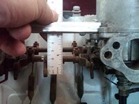
look now with full choke and you can see that it has lowered the seat that the needle rests in

if you look inside the carb air opening you can see a round cylinder that goes up and down and raises the tapered needle. the orifice it rest in is stationary unless the choke is "activated" i know how these carbs work but i am probably not the best at explaining it....but any way as the throttle opens the butterflys on the other side of that cylinder pressure/vacuum makes it rise and fall and raises and lowers tapered needle into the orifice in the black tubeand the gas flows. so pulling the "choke" up enrichens the fuel mixture by adding more gas since the tapered needle seat in the black tube is lowered
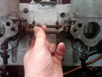
Last edited:
bobs77vet
Well-known member
accelerator cabling.....i used Barneys write up as a guide and it was spot on. i will say that this is the nosiest cable i have ever heard....nothing individually makes much noise the carb linkages are smooth and quiet, the cable is new and smooth, the pedal assembly is quiet but when its all hooked up it sounds like an old screen door, maybe not moving much in 30 some yrs is making it work out the rough spots
http://mgaguru.com/mgtech/carbs/cb115.htm
fitting the pedal stop turns out to be right at a half way setting at WOT
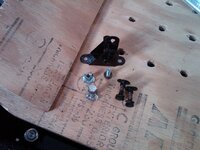
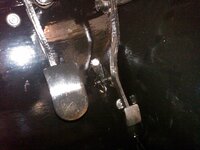
i have a temporary spring in place and will order the correct replacement spring i see no sense in trying to guess at this.

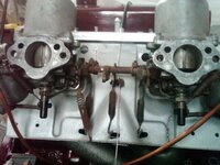
http://mgaguru.com/mgtech/carbs/cb115.htm
fitting the pedal stop turns out to be right at a half way setting at WOT


i have a temporary spring in place and will order the correct replacement spring i see no sense in trying to guess at this.


bobs77vet
Well-known member
bobs77vet
Well-known member
bobs77vet
Well-known member
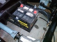
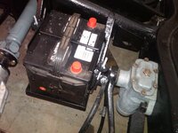
lets nibble on the battery cables....
heres how you crimp them
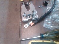
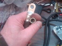
use self adhesive shrink wrap
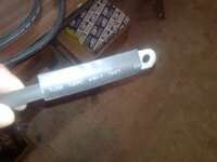
i made life a little more difficult for myself when i supersized the cable so how i have to remake the p clips....right now its just held in place with plastic p clips
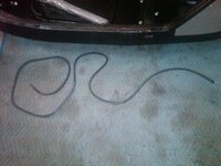
and the final routing I choose although you cant see it there is actually an air gap between the ground cable and the Pos cable. still need to get a red cover for the battery connection
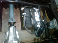
heres how you crimp them


use self adhesive shrink wrap

i made life a little more difficult for myself when i supersized the cable so how i have to remake the p clips....right now its just held in place with plastic p clips

and the final routing I choose although you cant see it there is actually an air gap between the ground cable and the Pos cable. still need to get a red cover for the battery connection

bobs77vet
Well-known member
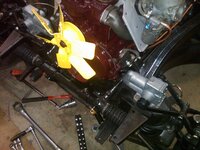
installed new felt seal, timing chain cover, ground strap, solenoid boots, fan and pully and starter
followed Barneys write up http://mgaguru.com/mgtech/engine/cs100.htm
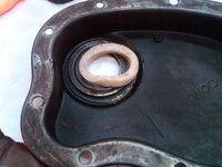
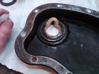
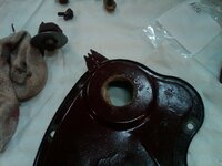
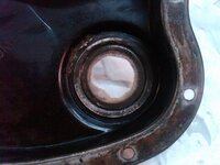
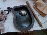
fan /pulley and ground strap
solenoid boots starter
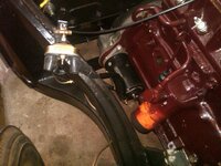
followed Barneys write up http://mgaguru.com/mgtech/engine/cs100.htm


fan /pulley and ground strap

solenoid boots starter

bobs77vet
Well-known member
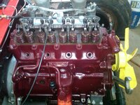
installed generator, coil, distributor and torqued crank pulley nut as much as i could once i see the pulleys spinning and can verify alignment i will fold the tabs onthe crank pully nut
removed fan and pulley to do this
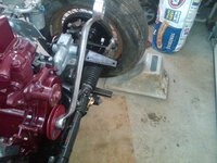
i put a big chuck under the tire and stepped on and put the car in 4th gear, the rear tire was spinning, so i guess thats as much it will get tightened
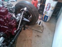
to install distributor follow through the compression cycle for #1 by watching the valves....they never lie
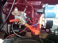
i used a fusible link on the power supply to the coil

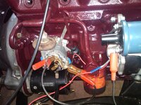
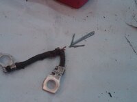
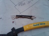
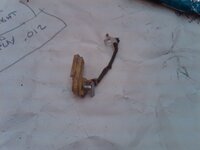
found a new problem when i went to static time the car.....it simply wouldnt work with a test light unless i went right to the points....so when i jumped the low tension lead inside the distributor i was able to make it work....so i need a new internal low tension lead.
removed fan and pulley to do this

i put a big chuck under the tire and stepped on and put the car in 4th gear, the rear tire was spinning, so i guess thats as much it will get tightened

to install distributor follow through the compression cycle for #1 by watching the valves....they never lie

i used a fusible link on the power supply to the coil


found a new problem when i went to static time the car.....it simply wouldnt work with a test light unless i went right to the points....so when i jumped the low tension lead inside the distributor i was able to make it work....so i need a new internal low tension lead.


bobs77vet
Well-known member
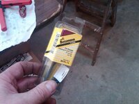
well found the problem with the low tension lead, and I made another to replace it, but the vacuum advance does not work. when i take it a part i can make it move freely, but it does not hold any vacuum or pull the spring when vacuum is applied. it needs to be replaced
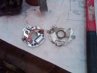
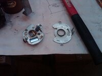
dirty but the mechanical advance moves freely
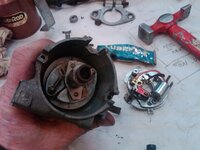
base plate is cleaned up now and moves freely but it would not move at all before
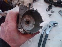
cleaned up shaft and housing

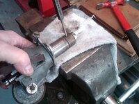
i notch the ends with file to make a "witness mark" so lining it up is 100%

driving out the tension pin
pretty dirty
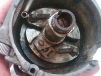
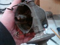
.012 end play i am guessing that is with in specs since its a straight shaft as opposed to a geared shaft like on SBC.
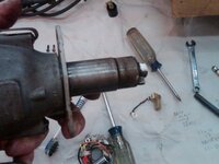
if you closely you can see where the low tension lead is broken
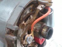
heres the model number
any body have a good vacuum cannister laying around?


dirty but the mechanical advance moves freely

base plate is cleaned up now and moves freely but it would not move at all before


cleaned up shaft and housing


i notch the ends with file to make a "witness mark" so lining it up is 100%

driving out the tension pin

pretty dirty


.012 end play i am guessing that is with in specs since its a straight shaft as opposed to a geared shaft like on SBC.

if you closely you can see where the low tension lead is broken

heres the model number

any body have a good vacuum cannister laying around?
bobs77vet
Well-known member
well for my purposes the old distributor with no working vacuum advance and a cobbled together low tension wire got installed tonight and staticlly timed.

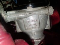
well the radiator that came with the car that is fugly but did not leak has a loose fitting
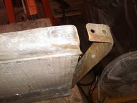
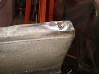
i cant tell you when i brazed something last but in any event this was one ugly looking braze repair. i used a flux coated brass rod
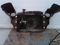
the scarey part is no alcohol was involved in this.....this gives me a visual mock up of where it needs to be, i will work on the bracketry fabrication next.
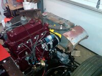
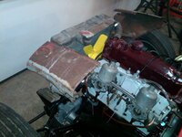
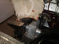
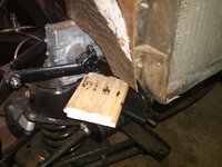
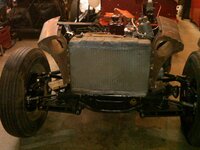
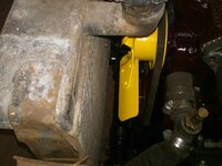

well the radiator that came with the car that is fugly but did not leak has a loose fitting

i cant tell you when i brazed something last but in any event this was one ugly looking braze repair. i used a flux coated brass rod

the scarey part is no alcohol was involved in this.....this gives me a visual mock up of where it needs to be, i will work on the bracketry fabrication next.


SuperBuickGuy
Well-known member
I hate brazing because I do it so rarely - I used to do it on a regular basis, so it looked really good.... not so much anymore - probably why I hate it now
:crutches:
:crutches:
bobs77vet
Well-known member
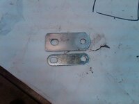
used 1/8 x 2 x 2 angle iron for the radiator support bracketry
make some transfer markings for the hole location
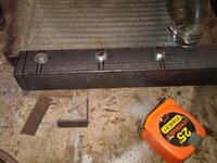
cut notch and drill lower support
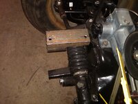
wheni had my garage made I had them make the floor level so i get pretty accurate reading on levels
making it plumb

not very fancy but really strong
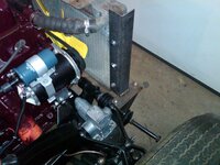
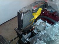
a quick glance and all i left to do is to hook up the oil pressure and water temp gauges and put the exhaust donut in place and i should be ready to fire her up....
make some transfer markings for the hole location

cut notch and drill lower support

wheni had my garage made I had them make the floor level so i get pretty accurate reading on levels
making it plumb

not very fancy but really strong


a quick glance and all i left to do is to hook up the oil pressure and water temp gauges and put the exhaust donut in place and i should be ready to fire her up....
bobs77vet
Well-known member
Latest posts
-
-
-
-
-
Was member years ago dropping by to say hello.
- Latest: crazyhorse
-
-
-
-
-

