Back To The Bonnet
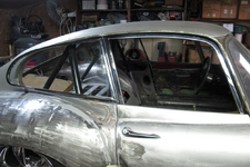
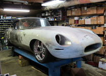
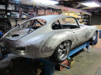
Having taken care of two major areas of concern, the rear fenders and the doors, I returned to the bonnet. As previously documented, all the metal work repairs have been done, it's hinged and sitting well. But it's far from complete.
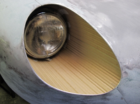
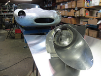
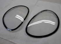
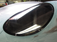
On the job list are covered headlight lenses. Out of curiosity, I spoke to the previous owner about the fact that the right fender had the Series I flanges to mount the lens yet the left fender and center section was straight cut metal, as if open headlights had been installed. He knew nothing of all that. Odd arrangement.
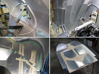
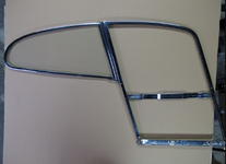
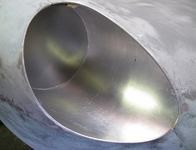
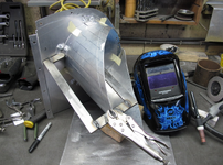
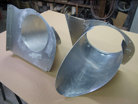
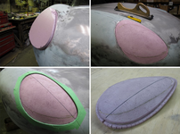
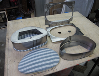
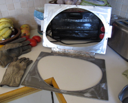
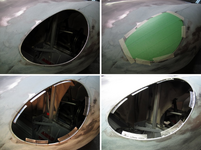
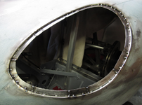
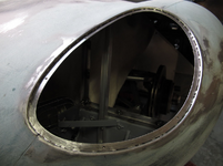
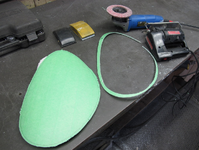
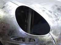
So starting from scratch, I needed to keep to a similar plan form to original for the lens and make both sides the same, mirror image. I got one chrome headlight trim ring with the car so from that and sizing up the opening that was there, both sides, I came up with a CAD piece to represent the flange I needed to fabricate.
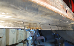
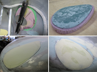
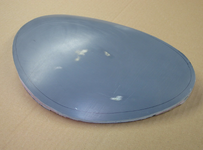
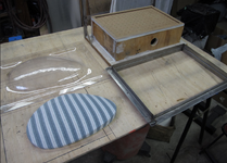
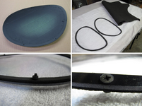
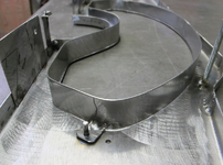
My plan was to bend 3/16" rod to the shape needed then weld it to the opening edge. I would add a sheet metal flange, stepped down after that, to match a formed acrylic custom formed lens.
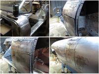
-CAD piece in place to trim metal
-3/16" rod bent and in place
-rod split at fender/center section
-shaped rod
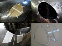
Welded in place:
Bonnet Assembly
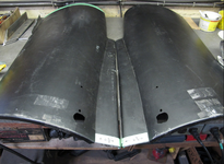
With all the metal work completed on the four bonnet panels, I was looking forward to finally getting it assembled. After a good cleaning, I sent it out to be epoxy primed.
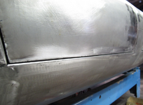
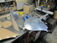
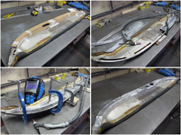
I was willing to add a reasonable amount of filler where the panels join in order to get a smooth transition from one to the other. In order achieve this and still be able to separate the panels, I slipped thin sheets of aluminum between them. The flange surfaces were finishes as well.
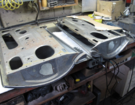
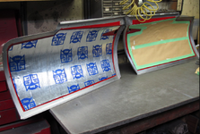
-panels cleaned
-louvers=time
-work area
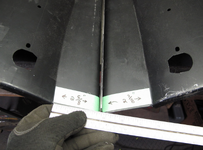
-panel dividers
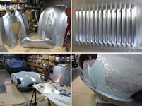
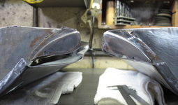
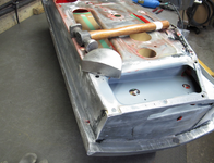
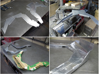
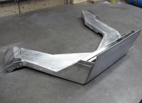
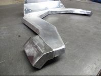
I also took this opportunity to final shape the lower valance. This would be very difficult to do while it's on the car and flipping the bonnet on its back is cumbersome.
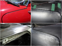
All the flanges were epoxy primed again before final assembly.
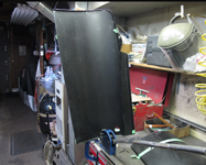
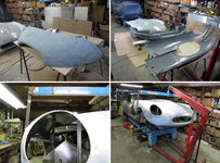
I had to reconfigure my bonnet lift now that it was in one piece.
-shaping lower valance
-epoxy prime all mating surfaces
-bonnet lifting point
-bonnet on the move
Bonnet Splash Panels
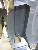
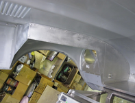
With the bonnet assembled and on the car, I could now proceed with fabricating the inner splash panels. These needed to line up with the lower splash panels already mounted to the chassis. The 1/16" aluminum panels would be mounted to 20 gauge angle brackets attached to the bonnet underside with adhesive.
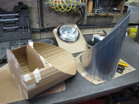
First step was to project up from the chassis panels and create a layout on the underside of the bonnet representing the placement of the bonnet panels. Along these lines, I cut cardboard, shaped to the bonnet and lining up with the chassis panels.
With these cardboard templates, I fabricated ¾" wide angle brackets with compound curves to match the shape of the bonnet. The compound curve required me to slice the one side of the angle and bend it inwards.
After test fitting the brackets to the bonnet, I fastened them to the panels temporarily then applied adhesive to the bonnet side of the bracket and secured it to the bonnet. Any discrepancies of fit would be taken up by the adhesive.
Originally, Jaguar fastened this type of bracket to the bonnet with a Sikaflex product. With some research within the Jaguar owner's community, I ended up using a 3M product, Marine Adhesive Sealant 5200.
With brackets attached, I drilled through the bracket/panel and used 3/16" blind rivets to assemble everything.
Please note: Particularly with these photo collages, click anywhere on the photo to blow it up to full size - in a new window. This new window can then be maximized for a still larger image.
-shaping angle brackets using shrinker/stretcher and slicing
-brackets next to cardboard template
-aluminum panel layout
-test fitting
