Guldstrand 5 Link, Anyone Anywhere Installed?

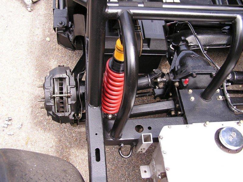
Yes, great article, learned a lot from it. I have the Forrest chassis that is mentioned in the article. That one day might be restored, not anytime soon . It was the first CVC Apex kit that was installed in a C3. Picture of the rear end is incorrect. It's of the John Caruso car, not the Herb Forest/Landis car.
Just a rolling chassis now. It was crashed hard at the Runoff's in 1984. Started life as a 69. David Landis built it in the 70's. Sold it to Herb Forest. Then to Mickey Agee. Found it in a shop in NC. Didnt know the full history when I bought the car.


Here it is with the 69 body before the 5 link was installed. And the way it looked before the RO crash.

83-1979SCCABP-CraigLieifheitatRdAmer.jpg


TN_Westwood-1980-09-07-083b1.jpg
 
Last edited:
I'm curious. Why have 4 attachment points per side? The reasons to rotate an axle is to change the pinion height, or pre-load.... but both of those reasons presume a solid axle.

The down side would be increased torque on a weaker point of the frame (the upper arm).

what am I missing?
 
The toe control is what they where after. Three different designs are in the pictures. Which one are you referring to? The Ryding, Rilley/Guldstrand and the Greenwood. Extensively raced in Gt1 when the SCCA allowed suspension mounting points to be relocated. Was used until the tube frame C4 killed the GM C3 framed racer. Look at picture 15 for the Ryding design. The Ryding mounts to the stock trailing arm location on the frame. You got to remember the roll cage attachment points and lots of frame bracing are done to these cars. These cars are far from stock. Greenwood, Rilley and Guldstrand built some of the most advanced chassis during that period. Ryding was a Engineer at GM and from what I understand, designed the C4 rear end.
 
Last edited:
Last edited:
I'm curious, what am I missing?


your missing that this rear suspension was designed to be SCCA legal.

then would there be other ways of modifying the frame/suspension to make it even better without going all the way to C4? (probably a dumb question, but I can't think of why quite yet - so be gentle)

The toe control is what they where after. Three different designs are in the pictures. Which one are you referring to? The Ryding, Rilley/Guldstrand and the Greenwood. Extensively raced in Gt1 when the SCCA allowed suspension mounting points to be relocated. Was used until the tube frame C4 killed the GM C3 framed racer. Look at picture 15 for the Ryding design. The Ryding mounts to the stock trailing arm location on the frame. You got to remember the roll cage attachment points and lots of frame bracing are done to these cars. These cars are far from stock. Greenwood, Rilley and Guldstrand built some of the most advanced chassis during that period. Ryding was a Engineer at GM and from what I understand, designed the C4 rear end.

I'm only asking about the links that run parallel to the frame - what is the advantage of having 4 points rather than 3? As a tangential question, to use a 5 link (4 points instead of 3, and presuming a roll bar), would you need to run a brace from the upper link attachment at the frame and triangulate to the frame at some point near the middle of the door?
 
SBG?

If you were to remove any one of those links the suspension would be inoperable. Assuming your talking the Guldstrand 5-link. If you had 1 forward link say like an OEM C3 trailing arm for one the upright would rotate a bit. Around the inner toe rods fixed point. When the upright rotates it will change the position of the two camber/toe rods in motion. When that happens the wheels start to toe. And my guess they would toe out. Then there's bind.


Here's a pic where someone tried to control toe on a C3 from behind the HS. Looks he tried to create RS like a C4. His home made links look longer than his HS's.
47685118d1322415525-red-scca-vintage-race-corvette-f6.jpg

Ralphy
 
Last edited:
Here is the first CVC kit as found. Was in kinda sad shape. The CVC kit was installed by David Landis. He used the Franklin quick change due to strength of the unit. The car was raced in a couple of 6hr endurance races. One was the 6 hours of Glens. The car was disassembled in 1984 and a lot of the parts were used to build a GT1 Camaro. Have found the Jongbloed's that where on the car. Plus the body molds for the 69 body. They are in PA.

2011-06-22095714.jpg


DSCF0805.jpg


DSCF0802.jpg
 
I'm curious, what am I missing?


your missing that this rear suspension was designed to be SCCA legal.

then would there be other ways of modifying the frame/suspension to make it even better without going all the way to C4? (probably a dumb question, but I can't think of why quite yet - so be gentle)

The toe control is what they where after. Three different designs are in the pictures. Which one are you referring to? The Ryding, Rilley/Guldstrand and the Greenwood. Extensively raced in Gt1 when the SCCA allowed suspension mounting points to be relocated. Was used until the tube frame C4 killed the GM C3 framed racer. Look at picture 15 for the Ryding design. The Ryding mounts to the stock trailing arm location on the frame. You got to remember the roll cage attachment points and lots of frame bracing are done to these cars. These cars are far from stock. Greenwood, Rilley and Guldstrand built some of the most advanced chassis during that period. Ryding was a Engineer at GM and from what I understand, designed the C4 rear end.

I'm only asking about the links that run parallel to the frame - what is the advantage of having 4 points rather than 3? As a tangential question, to use a 5 link (4 points instead of 3, and presuming a roll bar), would you need to run a brace from the upper link attachment at the frame and triangulate to the frame at some point near the middle of the door?

Good thoughts, but not much reason to reinvent these designs. They had their place in racing history. If you use a 5 link in the vintage series. As Redvette said, off to group 10. Thats the piranha tank for a C3
 
The reason for th 2 individual forward arms is 2 fold, one is to craete a virtual trailing arm that is much longer than the length of the 2 rods and the other is to keep the spindle upright...upright. Without that toe control is affected because the guldstrand system has 2 lower rods controlling camber and toe. For the greenwood setup it's similar but a little different since the toe control is on the rear in line with the halfshafts.

You have to seperate the forward arm and the hub to be able to have toe control from a seperate link. This means there has to be some sort of hinge that can articulate. How else would you do it but with 2 forward links? Double a arms..yes, something else? No
 
The two trailing links are a parallelogram. At first hard look I couldn't understand why the upper was forward of the lower. However looking at some of the pics you guys provided, I can see it's a clearance issue at the frame mount.


TT, I see a few guys are using the coilover mounts. Plus Dick G being pro coilover guy. I just look at that aluminum upright and wonder. Then the word cast as in casting comes in! Hmmm........... are those coilover ears going to take the pounding? But then you look at the assembly with the bearing housing bolted in place. Maybe it's all good.

If you were to add an additional link behind the HS exact.Similar to the C4. But same length same plane as the HS, would there be any benefit? I would think even being a little off wouldn't create much bind. This would guaranty, no twisting of the upright.
Ralphy
 
Last edited:
You can not use rear toe control without removing 1 of the lower rods. What you want is what greenwood did and what I built and scrapped years ago. The C4 is similar but the factory cheaped out by using a single center mount, the proper way would be to fab a bracket that would place the toe control rods behind the HS so they ahve the same operating plane and in line pivot points & same length.
 
What you want is what greenwood did and what I built and scrapped years ago.

I've been curious as to why you scrapped - or put aside development? In some clubs - relocating suspension points eliminates you from competition (some classes.) Was that a factor?

Cheers - Jim
 
You can not use rear toe control without removing 1 of the lower rods. What you want is what greenwood did and what I built and scrapped years ago. The C4 is similar but the factory cheaped out by using a single center mount, the proper way would be to fab a bracket that would place the toe control rods behind the HS so they ahve the same operating plane and in line pivot points & same length.

there's what I didn't understand - thanks TT

I pay in the dirt, so this pavement stuff seems a bit overwhelming at times... with a 5 link, it seemed to me that something would bind; but I also wondered if it didn't move that much, whether the binding problem didn't exist (again, I'm used to things with 16" of vertical compliance)
 
2-3 inches up and 2-3 inches down. Slip yoke half shafts.​

"Any suspension will do -- as long as you don't let it move." (attributed to Colin Chapman~ or similar enough...)

Any suspension, no matter how poorly designed, can be made to work reasonably well if you just stop it from moving. Colin Chapman
And this one:

"Make the suspension adjustable and they will adjust it wrong — look what they can do to a Weber carburetor in just a few moments of stupidity with a screwdriver. "

Cheers - Jim
 
Last edited:
2-3 inches up and 2-3 inches down. Slip yoke half shafts.

"Any suspension will do -- as long as you don't let it move." (attributed to Colin Chapman~ or similar enough...)

That concept was beaten into me by Kas Kastner, a Hero in Triumph racing circles. He slowly forced me to address motions and make the suspension work over a range of travel. The things I do are foreign to most of our racers and I long ago stopped arguing the points. But my car drives around the competitors now and they put it down to horsepower.
Not Corvette related directly but the point is valid, make the suspension work and the horsepower is a welcome addition.
 
Roger That!
It all needs to play in symphony. Balance: control/power/skill/fear/preparation/luck.
I bet that list goes on and on.

And when in the Mud and Rocks -- you'll need a Heap of travel - and compliance. Else you'll be stuck on a pile of rubble spinning like a top!
Cheers - Jim
 
Which project TT? Is there a thread here?

I posted this pic once before due to the fact he is using a C3 diff. Here's a guy who feels he found the sweet spot and 4 point mounted his upright. He had a restoration guy build it. I don't disagree with you however I still wonder.
MichaelZappa-TVR-Tuscan-DI.jpg
http://www.britishracecar.com/MichaelZappa-TVR-Tuscan.htm

"Ultimately, the frame would receive many modifications, including entirely custom front and rear suspension pick-up points. Much of his chassis work was subcontracted by Mike Zappa to his friend Mike Pierro. Mike Pierro is also located in the Pittsburgh area, where he specializes in restoration of Cobras and GT40's. His shop is known as MAP Automotive. MAP Automotive restored the TVR tubular chassis, built the rollcage, fitted the engine and radiator, and fabricated the custom exhaust headers."
 
Last edited:
This is under my C3.... and the drawings are avalaibles at Vettemod.

thum_1449b5aa745dcc2.jpg

If you click the pic you can check some other pic of the system.
By the way now I have Penske coilovers instead of QA1.... QA1 have very poor control and quality.

The system is my own design, and in 4 years I don't have noticed any problem even driving at the track.
Of course the quality of the rodends must be very good (again NOT QA1)

...just my two cents...
 

Latest posts

Back
Top