Guldstrand 5 Link, Anyone Anywhere Installed?

First of all in 90% of cases the upper arm should be some 30% shorter than the lower one.... this will give you some bump camber gain.
Theoretically you need same camber gaing than the roll angle you will have, in order to keep the angle between tire and ground constant.

I allways like to have more camber gain than body roll because the more roll mean higher side load (assuming constant your roll stifness) with the consequent higher tire wall deflection.

Unless you will use your car at the strip, the longitudinal link angle isn't a big concern.
As I told you before the antisquat in a race is important only one time (at the start)..... otherwise the wheel hop when braking will be important before each corner! ;-)

Back to the toe link..... the lenght is only a small one of the parameters of a well designed suspension.
The bump steer will be conditioned by the lenght of the links, by the position of the internal pivot points and even by the king pin angle of your spindle (relative position of the external pivot positions).

Many many different configurations will give you the same bump steer result.

By the way the more important parameter of ANY suspension is the movement of the roll center according with the suspension stroke.

You will have to design a system able to warrant a minimal side travel of the roll center and, as a second issue, an acceptable vertical movement of the roll center in relation to the ground level (this thing is less important).

Only now you can define the correct toe link to warrant the correct roll steer (which is not allways zero roll steer) according with the combo above defined.

As per engines, in this job you will be allways in the "short blanket" condition:

If your nose is well covered, your feet will not....
If your feet are well covered, you will freeze your nose !

Is easy to believe in that, because on the contrary any race car will have the same suspension design!

The job is to obtain the best compromise for your needs!!!!!
 
Last edited:
But doesn't the longitudinal links length and their angle affect chassis roll when cornering in a power on or braking condition? Throttling out of a turn this angular condition of the inner side of the chassis would tend to create more roll? Since the inners are pointing higher and at the outer wheel there lower. Hence the reason you see long longitudinal/trailing rods on cars such as the GT40. Moving the point out as long as possible reduces angles and any push or pull comes from a more centered front to rear point. Making these links less effect at disrupting a chassis free motion.

Claus Arning said of the C2/C3, it does so many things wrong. Toeing the wheels out and shortening the wheel base. Something like that. Arning built his T5 IRS Mustang/Falcon suspension from some Corvette parts. Love it, Chevy on a Ford!

gt40_paint_016.jpg

index.php


If you look at the NASCAR truck arms they put them way forward and almost center axis. Allowing the chassis as free a motion with minimal torque or brake effect on it. It's just plain harder to lift, pull down or roll a chassis from the center. Which is good?

attachment.jpg

As far as the roll center I completely agree! Phantomjock really helped me understand the topic a lot. Along with roll axis angle and whys.
 
Last edited:
When I talk about anti-squat and wheel-hop I mean exactely this thing!

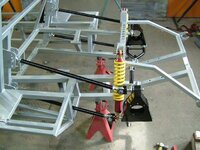
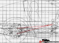
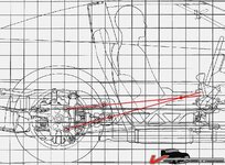
Remember that the front pivot points aren't the point where the links act..... the two links are like a big long single link starting from the wheel hub and ending in the point where they should intersect..... so two parallel links are like an infinite long arm.

This is named "longitudinal swing arm".

Coming to the Nascar truck example, you don't have to be confused between live axles and IRS.

The forces resulting in a live axle during acceleration and braking are applied to the axle and to the frame via the suspension links.... in a IRS system the forces are closed in the differential supports, so these forces aren't working in the suspension links.
 
That's the virtual arm I have been talking about also, the instantaneous center where the 2 arms intersect gives you th effective swing arm lenght. The point is not steady but the arm is lond and care should be taken so it doesn't move around too much.
 
Two of the critical components for this are Length and Location. Else - you wind up with the "standard" C3 solution - that acts as a single attachment point and generates all those unhelpful challenges to the IRS we are trying to eliminate - through a variety of approaches!

Cheers - Jim
 
The visual diagram showing the two trailing links with lines drawn to a vectored/IC point? To me shows nothing more than a static point/direction of force based on all things being equal. It would seem to me I can make that visual useless. An example of what I mean is to move the axle center line off center. Say 1" from the lower link and 5" from the upper, still between. App. 84% of the load is being sent through the lower link right? Where do you draw the line and point now? And how do you have a direction of force pin pointed in this example? But now somehow if I make my links parallel, all the directional loading disappears? What I imagine with parallel links. Is that you would now draw the line from the center line of the axle straight out inline of the links. And that is the direction of force.

Another way to look at what I'm trying to convey. Build a setup with the trailing links going downward on the passenger side at 20 degrees. Then on the drivers side reverse them upward 20 degrees. Now from a standing start hammer the throttle and go. Won't the chassis/car want to roll at the rear? Better yet throttle out of a left hand turn. What am I missing here? This is the same scenario you have cornering. However not as drastic. One side increasing it's angle the other decreasing. Being in our type of cars and not being able to extend forward. Is it wise to go backwards with the upright mounting point? More length would give less angular change in regard to jounce and rebound.

Sorry if I sound like an ass!

Ralphy
 
Last edited:
.... in a IRS system the forces are closed in the differential supports, so these forces aren't working in the suspension links.


okay, I'm lurking and I admit it. However I was following along, but something got lost to me in the translation - what do you mean by "the forces are closed"?
 
.... in a IRS system the forces are closed in the differential supports, so these forces aren't working in the suspension links.


okay, I'm lurking and I admit it. However I was following along, but something got lost to me in the translation - what do you mean by "the forces are closed"?

A solid axle has the entire housing free from the chassis. The pinion gear trying to climb the ring gear generates high lbs. forces. In this design you can direct this high load to create anti-squat. An IRS has the carrier fixed so all that energy is removed from the suspension.


Here's where I have problems understanding. Remember that the front pivot points aren't the point where the links (act.....) the two links are like a big long single link starting from the wheel hub and ending in the point where they should intersect..... so two parallel links are like an infinite long arm.


Seems to me the link ends are where they act. It's not however the direction of the force. It would be at the IC of the two links. But unlike a true elongated trailing arm reacting and moving from the IC point, the IC point itself moves.
Ralphy

Here's a video I found of a guy who put a C4 IRS in a BMW. You can't see any trailing links. However watch what happens at app. 30 seconds. If your looking to do super duper hole shots, an IRS is probably not for you. He goes from a rolling start.

[ame]http://www.youtube.com/watch?v=XvxLdSQxwP0&feature=related[/ame]

Stroker,
I know of a guy running a C4 IRS in a AC Cobra kit with parallel TL's. He runs big springs also, app. 750 lbs. This is in a car that weighs around 2,400 lbs. and 50/50 front to rear weight bias. He does track his car.
 
Last edited:
good video

however, with the guldstrand you should be able to dial that out.... not so much with the C4 because it doesn't have the ability to change the instant center

I kind of presumed that was what he was saying, but that leads to the question it raised to me. Yes, you have rotational forces from the nose of the carrier trying to go through the floorboard; but you also have rotational forces of the motor lifting the front, left wheel and planting the right.... he said the forces are the same - but they're not. The force is still there, but its action on the car is different.

I'm still learning all of the suspension stuff - but the most basic rule that helps me is 1) identify the force at work, 2) determine what it's doing, 3) use it to your advantage (if possible). With the stock C3 suspension the suspension rebounds as badly as my 70 Buick Skylark - so even though I'm building the car for the same purpose (autocross), I need to eliminate that because I will have enough power and traction to cause axle hop even at speed

So are they the same? unnoticable because they're put in a different place? or different?
 
I'm confused as usual. The video above shows the car squating at :30. To me, I think that indicates that the trailing link intersection is abave the CG. If they were below, the car would jack, correct?

448c9acb7aed90.jpg

I don't understand how parallel links would be of benfit. The forces generated would (even if centered at the CG @ ride height) move above and below center with suspension travel. The intersecting links move also but not like the parallel.
 
My guess first would be the car is squatting because the amount of anti-squat that can be generated is minimal even with the OEM configuration. Plus he may be using too light of a spring. Next you need to define what is the strong suit you wish for your suspension. The same anti-squat you may wish for will negatively affect cornering. A road race is not won by the guy who gets the best hole shot, that's not the race.

The goal for a good corner carver should be to allow the suspension at all times to move freely. Let the spring be the spring. Dial out geometry negative effects. Just because a car squats it doesn't mean it's not getting any weight transfer to the rears. The most common issue I see is wheel hop in regard to an IRS.

The only reason I posted the NASCAR pic was as an illustration. Put a jack right under the perfect center axis point of a chassis and jack the car up a few inches. Now go to any corner of the car and push down on it. You can freely move any corner you want. That is why they put the truck arms where they do. That point negates any adverse effect on the suspension better than any other point. The suspension as best, stays free of any throttle or braking effects.

As far as parallel links? My guess is the unseen infinite IC moves around less.

That's my take at least!


Ralphy
 
Last edited:
The parallel links is a possible option.... as I told before, when using very stiff springs this part of the suspension is not a big concern.

In the 60' nearly all formula1 cars used parallel longitudinal links.... even pointing to the ground.

Sorry for my english, I'm doing my best but sometime is quite hard to me to explane my mind!

no worries on the translation - if it doesn't make sense, I'll simply ask; thanks for your knowledge
 
I'm confused as usual. The video above shows the car squating at :30. To me, I think that indicates that the trailing link intersection is abave the CG. If they were below, the car would jack, correct?

448c9acb7aed90.jpg

I don't understand how parallel links would be of benfit. The forces generated would (even if centered at the CG @ ride height) move above and below center with suspension travel. The intersecting links move also but not like the parallel.

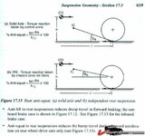
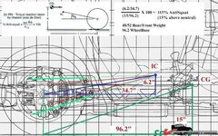
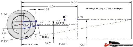
No, if you lower the IC of the virtual arm it will increase the squatting. The problem is, the torque reaction is not in the suyspension but in the diff and it's hung on the sprung section of the car. You can not get close to 100% or more anti squat (more giving lift) ad have a realistic forward arm configuration with acceptable bump characteristics....so it will always squat down.

As a result of the tq reaction being in the diff the schematic for calculating anti squat is different, the "pole vaulter" analysis is not based off the tire contact patch but off the axle center.


25060d1d00c402.jpg

25060d1d03e0ed.jpg

25060d1d06a40e.jpg
 
I'll try and find the picture. A Cobra guy bought a car with a C3 IRS. The builder lowered the front mounting point of a OEM C3 trailing arm approximately 5 to 6 inches. The new owner said every time he accelerated hard the rear would squat. Squat so hard the suspension would bottom out. It's no wonder.

My memory is bad. He has a C4 and he had lowered links on it. It looks like he removed the pics related to his issues since he has changed his setup.

Stroker, I only wish I could do as well as you with another language.

You can still see a bracket where both trailing links mounted, yes both. Way to the right of the picture. The axle center line is app. 3" or 4" above the 4" box tube.

You can barely see the lower links front mounted below the camber rod.
http://www.clubcobra.com/forums/mem...ms-misc-picture4536-rear-suspension-pass.html

http://www.clubcobra.com/forums/members/rawkkrawler-albums-rebuild-picture6115-old-glass-trunk.html

http://www.clubcobra.com/forums/album.php?albumid=836

Ralphy
 
Last edited:
I love how I can lurk and learn - so that's why I have axle hop; I lowered my C3 about 4" and the arms are no longer parallel with the ground.

I'm waiting for the last pieces and I'll be doing a Guldstrand suspension in my C3 (thanks for the CAD drawings). Also on the CAD drawings, make sure your laser cutter can use metric - apparently the company I use bought a German machine that requires expensive, additional software to use metric (weird huh?). The work around is I have to give them a dimension and they extrapolate - but it's a PITA for both of us. TO BE CLEAR, I'M NOT COMPLAINING simply noting something that is both weird and can come up.
 
SuperBuickGuy,

That's not the only thing. Your roll center has been changed front and rear. At what angle are your half shafts? Can you put your car back to factory height? Half shafts should be level.

Ralphy
 
half shafts are not level, but they're the right way of not being level....

here's my car at ride height
P9250002.jpg

ignore the interference fit sway bar, that was today's project to fix.... and it's fixed(ish)
 
Last edited:
I'm confused, I thought you lowered your car? At proper ride height shouldn't the HS's be level? Looks like your sitting high not low? What size are your tires and wheels? Is that a steel body car?

Ralphy
 
Last edited:

Latest posts

Back
Top