new build pics of 409

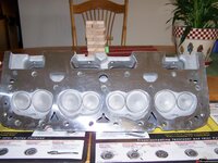
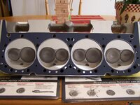
OK. Here are pics of one of the heads. They are Brodix IK200. The head gasket is a fel pro 1004.
384fc176dcdbc4a.jpg
384fc176dee1e56.jpg
384fc176dfdfbb6.jpg

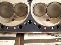
Close up of the water passage between the 2 center cylinders. NOTE. i have not drilled out ant of the gasket passages yet,thats next on the list of things to do.
384fc176e0dc125.jpg

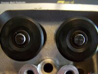
testing for push rod length. look OK? the right is intake,left is exhaust.
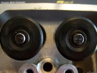
384fc176dde511f.jpg


Wow with the hole not being drilled in the center of the decks that would cause a lot of water restriction in the center head from what I can tell, Try putting the gasket on the block and see how it looks?
 
I've been doing some research on this. I knew i had seen something on this before. I have 2 chevy power manuals 5th ed and 7th ed. The 7th edition page 62 has a note and drawings on this mod. I tried taking a picture of the page but that came out terrible. I'll try and scan later. Its almost impossible to understand without the drawings.

There are 2 ways to do it. Both methods require the same head drilling plan. I don't think anyone but a machine shop who has done this before should even try. Someone who has done many of them. Carl??

The two holes must intersect to form a V shaped passage in the head that come close to the center 2 exhaust valves. Its a cooling stream. If the holes are not drilled perfectly they will not intersect and you have a failure. The holes go deep into the head all the way through the cooling jacket.

Howards setup is a little harder to do. The upper hole that penetrates the water jacket must be tubed (ie sealed off from the water jacket) otherwise you have nothing but a connection from one part of the water jacket to another where there will not be any differential pressure. So once you have the hole drilled, you have to press in a tube/sleeve. The higher pressure coolant from the pump flows into the top hole passing through the water jacket via the tube where the coolant flows to the intersection with the other hole then reverses path back and empties into the water jacket where the pressure is lower.

The second method supplies coolant from the normal hole in the deck. The head's coolant passage has to be tapped and plugged (in addition to the previous 2 holes being drilled) to force coolant to flow through the custom drilled V passage. This forces coolant from the deck in the reverse direction (from the above method) through the V shaped drilled passage.

Like i said you really have to study the drawings for about 30 minutes to understand the whole thing.

I apologize for any confusion i might have created earlier. This mod has NOTHING to do with the steam hole mods that are often drilled in the heads on siamesed blocks.

The scan should now be attached. You need to download and zoom in to see the drawings.
 

Attachments

  • EPSON001.JPG
    EPSON001.JPG
    631.4 KB · Views: 18
Last edited:
All holes have been drilled. In the deck and the head gasket.
384fc3e6e7dae72.jpg
384fc3e6e8da9dc.jpg
384fc3e6e9dccbe.jpg

This is not my idea of a good time,but it came in within a 1/2 degree.
384fc3e6eacf991.jpg
 
Are you planning on dynoing this engine before installing?

I would like to. BUT,i do not have one or know anybody that has one.
Here is a question. fuel pump push rod,comp cam 4607.will fit up the bore about a 1/2 inch and then gets stuck. now if you flip it around and send the wrong end up,it will fit. i guess the end that rides on the cam,looks to be bronze,is a bigger diameter.
Any suggestions??
 
Last edited:
Are you planning on dynoing this engine before installing?

I would like to. BUT,i do not have one or know anybody that has one.
Here is a question. fuel pump push rod,comp cam 4607.will fit up the bore about a 1/2 inch and then gets stuck. now if you flip it around and send the wrong end up,it will fit. i guess the end that rides on the cam,looks to be copper,is a bigger diameter.
Any suggestions??

It's been dropped on the bronze end. Throw it in the trash. You don't need it.
I don't need it, as in, i don't need a push rod? OR i don't need one with a bronze end?

Just went out and tried it in the motor i pulled out, and it fits just fine in that block. and the push rod out of the old motor fits in the new motor. I do have to have the bronze tip for this cam.
 
Last edited:
I do have to have the bronze tip for this cam.

Those cam manufacturers say the same BS about bronze dizzy gears, and they aren't necessary either.
You have seen what happens to those POS gears also.
 
Have you seen what happens to stock gears? Just get a billet cam with a pressed on cast iron end.
 
I do have to have the bronze tip for this cam.

Those cam manufacturers say the same BS about bronze dizzy gears, and they aren't necessary either.
You have seen what happens to those POS gears also.

OK. I will use the push rod out of the old motor then. and if eats the cam, there is $400.00 gone. thats how much that cam cost.

Im gonna call comp.
 

Latest posts

Back
Top