Project Elvira – Intro and Update

John is a phone guy. He has "people" that will answer email, and may keep the site "warm" but he is the guy.:thumbs:

Today's post in a bit
Cheers - Jim
 
Pappy -

yeah I like the Cheetah. Always liked but understad they had some real bad oversteer habits. I copied some of my gullwing mod from it too.

Here is a summary on a topic that is important to my build. Seems like a good place to insert here, just now.

DROP SPINDLES

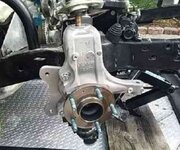
There have been some questions regarding this in years past, and seems like a number of options are now coming available. One idea that I decided to implement - after a number of posts elsewhere here is using the C7 spindle. It adds a lot of drop over a typical C3 spindle. The bearing is mounted higher in the upright relative to the bearing, and the lower a-arm mounts below the hub, not "inside" like on a C3. I called Tim Savitske to get some ball joint taper details and when we started talking about using C5/6/7 for front end he was very discouraging about the trip down the rabbit-hole. I told him I was mad or insane and it didn't matter. He let me go asking to see how it turns out. BTW he does have a lot of other options, but I was already committed.

Here are some interesting notes from an outfit that makes a variety of drop spindles for other model Chevys (A body etc), maybe you'll find it interesting:

How do I know how much spindle height I need? UMI has a number of solutions to the A-body spindle height problem. Most of them utilize the factory GM spindle and a combination of ball joint heights. We are happy to discuss tall spindle applications as well. Please call the tech line at 814-376-6000 or email [email protected].

½” taller upper and standard height lower – when combined with a 1 or 2 inch lowering spring, this cost effective option helps your daily driver perform better when cornering at everyday speeds. If your car squeals the front tires on exit ramps, this mod is for you.

0.9” taller upper and standard height lower – this option is for the corner carver looking to add almost an inch of spindle height at a very nice price point. A 0.9” tall ball joint setup helps control camber on fast corners without breaking the bank. No modifications are needed to the lower a-arm which makes the UMI upper a very attractive and easy to install item.

0.9” taller upper and ½” taller lower – with a total of 1.4 inches additional spindle height, the 0.9/0.5 package is intended for auto-x and track use. The camber curve is quite aggressive and really helps plant the tire properly during suspension travel. A 1.4 car can use a very mild static alignment and have great grip in the turns. The 0.9/0.5 package is awesome for Pro Tour style cars destined for long trips combined with track duty. A true high performance suspension for sure.

Not associated, just passing along. I bet they might be helpful given the range of options on their web site (but no C3 directly.)

Using a combination of a drop spindle, and tall ball joints, a lot of options open up.

Enjoy. I'll be adding some details on the front uprights early morning.

Cheers - Jim
 
So, here we go. I've had my first cup of coffee, and hope I'm ready to type.

FRONT SUSPENSION

The upper a-arms are the SPC adjustables. I've added Howe Tall Ball Joints to work camber gain. Can't say I need to yet, but building it in -- you know -- while I'm at it. 126951fb928bbe491.jpg

I pressed out the "standard" C7 upper ball joints, and had "slugs" machined for the upper ball joint mount:
12695d18cfaea1614.jpg

If anybody needs some of these, now that the code is run and a fixture made for the cnc you can get a better deal. Just ask and I'll get you the details.

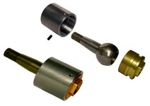
For the bottom of the upright, I drilled/reamed the lowers to meet a 10 degree tapered 6141 ball joint. The ones I chose are rebuildable circle track gear from Coleman Racing.
27653-color.jpg

One of the things Ron Sutton advises is to have a means of adjusting the roll center. These are not the easiest way, but do-able. On the lower control arm, I removed the original lower ball joint and welded in the Coleman Racing "barrels." There is some "slight interference with the transverse spring outer on mount lower arms. This was resolved using a slightly smaller washer.

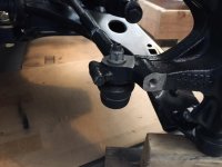
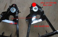
The Vette Brake lowers needed a mod for the Dual Coil Over adjust shocks as well as drill out the ball joint for the replacements. Kinda' like this:
12695d18f2efc41a4.jpg

The real challenges are yet to be faced, brakes and steering on the front. Some fun on the horizon -- I'm pretty sure. You can see I did a bit of a tease in the upright image - the brake bracket. More on that later.

Cheers - Jim

:yahoo:EVERYBODY have a GREAT 4th of July! :yahoo:
 
Last edited:
Y'all get a double dose today as I do some catch-up.


STEERING/BUMP STEER & ROLL CENTER

Steering is important - even though so far we have yet to fire the engine. And, the transmission needs some finish work too - so it is more or less a "push-car." With the winch dead, it took us almost 2 hours to get it on the trailer! Wheels go one way, then the other. Push chock the car, straighten the wheels, push, chock. Repeat until complete. Though of using the trailer as an oversized shovel! Grunt, groan and 2 aspirin later the job was done. Then a trip to HF to buy a new winch. (Yet to install - not needed just yet)

Now I can get back on to the build.

Having shoved the engine back 13 inches gave me a lot of space not only for the radiator duct/airbox, but also a chance to think about mounting the rack and pinion in a front steer/upper mount. The front steer was going to present its own problems down low with the transverse spring and the lower a-arms. Building a new K-Member could be a solution - but ohh what a job. So up top it must be. Now what challenges exist there?

I've done a bit of roll center calcs off and on during this build. There is a lot to sort out including Bump Steer, Ackerman, Scrub Radius, etc. You can learn a lot over at Pro-Touring and Lateral-G from Ron Sutton. But at some point I just gotta "cut metal." Well, maybe do some modeling first, but gotta' get going.

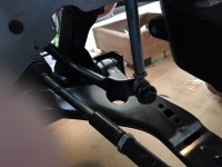
I've used a variety of programs and graphics to sort out the "planned" RC and instant centers on the front end. So, with the front raised to reach max droop, I made a quick measurement using a few metal rods. Nothing like trying to get the truth over modeling assumptions:
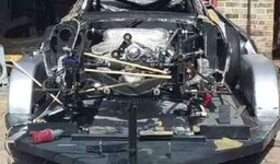
12695d18cfaec45a7.jpg In this pic you can see the rack is sitting on the chassis arms, and the rods are aligned with the steering arm (tie rod) and the UCA and LCA, and even spot the approximate RC - when at full droop. I wanted to check full droop to ensure the upper mount of the tie rods wouldn't hit the chassis arms. At full compression, I would certainly clear the chassis.

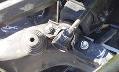
With this information I was then quite surprised. The Grand Am rack is almost perfect width. Some judicious cut and grind on a couple of chassis tabs, and cut the rubber mount on the rack a bit -- and it FIT! At last, a break. (Maybe...)
12695d1d0f4b139b7.jpg

Now to just work out bump steer and...OOPS! The steering arm on the C7 would put the balljoint right into the tire! ARGHH. (And that is with only 2 inches back space!)

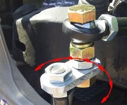
This is the approach I planned, but need to wait on some solid rod ends (back-ordered) to complete. I'd use those to make an offset for the steering joint. Basically look a bit like this:
12695d18f2efc41a4.jpg

Most likely adding an offset spacer to get things where they need to be. 12695d190568efa35.jpg
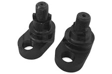
These "RACK EXTENDERS" are used a lot in drift cars, so there are so available. Think I'll do some modeling. Back to the drawing board (CAD)!

Ahh, what the hell. I had a sizeable plate of aluminum, so cut out a piece to fabricate a set of Tie-Rod-Extenders. No fancy CAD here, just some TLAR - That Looks About Right. Pappy gets it I'm sure. And more that a few on the board have experienced it too. A run to Fastenal for some sizeable nuts and bolts, and - voilla! I have made the extensions!
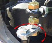
12695d1e137339b05.jpg

Quite nice, even if saying so myself! :thumbs:

BUT... This little bastard has been killing me!
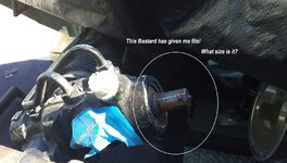
12695d1d0f4aef1fb.jpg

I need a U-Joint:
Sweet-Mfg-U-Joint-3-4-In-Round-to-1-In-DD-GM-Column-Universal,31393.html


I've been all over this board, other vette sites, the inter-web and the 39 pages of Karsten's pdf and post. I cannot find the right U-Joint for the rack! I'm connecting to a DD - so that end is GTG-and plenty of options available. Karsten used a 17mm end on his - but that may have been at the 'vette column end - not the rack. It is NOT 17mm, and NOT 3/4" either.

I have had little luck in sourcing a joint. ANY IDEAS?

Meanwhile - everyone have a safe and Happy 4th of July. :bestwishes:

Cheers - Jim
 
Last edited:
Jim,

Woodward has a pretty good selection of u-joints, if you can figure out what size it is. Your tie rod extenders look like they will work, but you will need to calculate (or measure) what that change in geometry does to your Ackermann. A way to adjust Ackermann (if you need to) is to move the rack forward or aft. Where are you trying to get your RC? I use .75-1.0 inch above ground with full compression (splitter on the ground), and I just let the RC be what it is at ride height - you don't corner at ride height so I shoot for the proper dynamic relationship. Fortunately, I don't have a lot of roll center migration with travel, so all is well.

Looking good!

Pappy
 
Last edited:
Jim,

FWIW, I built longer control arms for my Focus track car, which required longer tie rods. I cut the end off the tie rod, had it threaded (14mm, in this case) and got another set of tie rods, cut the outboard ends off, and had them threaded. I then made a threaded sleeve that I screwed the ends of the tie rods into to get the length I needed. I further pinned each end of the sleeve with a roll pin just to make sure nothing moved. This allowed me to keep the Ackermann as it was. Here are a couple of photos.

Focus R&P sway bar end.jpg

Focus R&P tie rod end.jpg
 
Pappy asked for more - in Vegas and Phoenix he gets a "dry heat." Not so here in the Panhandle. So, I'm at it but slow.........Cheers - Jim

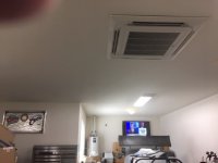
Here's how you handle the dry heat - a 3.7 ton dedicated garage air conditioner...and note the Coors sign. There is an appropriately-sized beer refrigerator in the corner.

Air Conditioner.jpg
 
Are you using a Grand Am rack in a front steer setup?

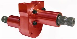
I used a steering coupler shaft from a late C4 with my Grand Am rack. They are both the same (rack shaft size)
 
Yes - Grand Am in a front steer mated to the C7 uprights.
Thanks for the head's up for a C4 linka. Gives me more to check out.

I'm off to search... Pappy - thanks for the link, but no joy at Woodward.

Others?

Cheers - Jim
 
Pappy - I "think" I can make "some" Ackerman adjustments with the tierod extensions. It should effectively be the same as shifting the rack fore/aft. "Fingers crossed!
12695d1e137339b05.jpg


BBShark - thanks for the tip-- found a piece on eBay - cheap enough - we'll soon know if that is the ticket!


Cheers - Jim
 
Hmmm. Its early this morning - but what the heck, I'll check after breakfast and see if i'm on the quest for a "different" part. I did trial on the setup and was pleased to see both moved correctly. But, I may have missed a key detail. Will know soon enough. I may have some components that will be excess to requirement!
 
Added a piece of bar stock to check steering - and both wheels turn! Yep - Just as suspected - opposite of desired. :bomb:
Rather than toss a wrench across the garage - or :banghead:

I went for a walk and sorted out a list of alternatives. (Yes my NEPA training has paid off). Too early for a whiskey.

1. Do Nothing -- No cost but have to learn to steer opposite of where I want to go
2. Fabricate a Bellcrank that with a linkage and rods beneath the rack, effectively "flip" the steering -- easy build - complicated install
3. Flip to Right Hand Drive -- Very interesting, some complications but I have years of RHD experience -- creates a novel look too
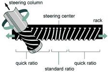
4. Rebuild the Rack and "flip the internals" -- may be do-able, may not

VGRS_Honda_VGR.jpg
5. Buy another Rack for Front Steer -- another OOPS, and bits to sell off
6. Return to "Original Setup" Flip the uprights side-to-side, but complications as per before
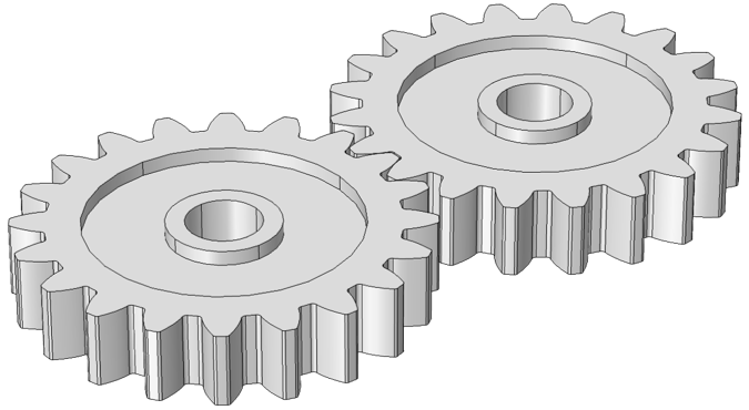
7. Make a Gear Drive Box to effectively switch CCW to CW and vice versa --I have some gears too

External-spur-gears.png

Well I have made a choice. Some waiting involved, but it will be Alternative #7, Gear Box. This is a trick (again) used by circle track guys, to mod front/rear steer.
30700-Color.jpg
Part should be in next week sometime. Simple enough to mount anywhere in the column. "I'd rather be lucky than good!" Just moving sideways--not backwards (just yet...)

When parts arrive later this week, including; new U-Joint,gear box, I'll get that all installed.

Cheers - Jim
 
Learning to drive it that way would be interesting. I saw a guy that had geared handlebars (so it steered backwards) on a bicycle in Austin once. He would bet people $20 they couldn't ride it across a line about 20ft away. I was hilarious, I saw about 10 people try. No one did it.

I looked at changing to front steer. The appeal of the CTO rack is you can dial in bump steer so well. Couldnt find any CTO front steer racks. But I did consider taking a C4 rack, remove the tie rods and connect a plate that was connected to both ends. Then connect the longer tie rods to that plate (similar to the Grand Am rack plates. I think that is doable as the C4 rack is only about 24 inches long.
 
I once did some work on the sailboat steering quadrant. It went over a couple of days, and when we hooked it all up, we went to leave the anchorage. But, the quad was, yep - backwards.

I tried and tried to "get my head around it", then just faced aft and took verbal steering directions. Don't think I'd really try in a car!

I was looking at some rebuilt C4s with just the idea you mentioned. The short 24" makes mounting options better. The I found the other alternative -- and it will be here Monday/Tuesday, and I'll be back at it. BTW the "drop" in that device will help clear the dash roll bar--good thing I have a small wheel.

Cheers - Jim
 
I once did some work on the sailboat steering quadrant. It went over a couple of days, and when we hooked it all up, we went to leave the anchorage. But, the quad was, yep - backwards.

I tried and tried to "get my head around it", then just faced aft and took verbal steering directions. Don't think I'd really try in a car!

Cheers - Jim

We lost an F-15 at Spangdahlem AB when they hooked up the hydraulic lines to the horizontal stabilizer backwards. The pilot, a friend of mine, almost figured it out on takeoff when the flight controls were backwards - push forward on the stick to go up..., but he finally lost it and crashed off the end of the runway. After that, they changed the fittings on the stab actuator so you could not hook them up backwards.
 
Are you using a Grand Am rack in a front steer setup?

I used a steering coupler shaft from a late C4 with my Grand Am rack. They are both the same (rack shaft size)

You caught the details I missed.

OP: I'm just curious Is the front steer that big of a plus (given the lack of bushing deflection in your setup). Given that the engine is that far back (making rack packaging easier), does it make sense to go to rear steer mode for even better weight distribution?
 
Last edited:

Latest posts

Back
Top