Project Elvira – Intro and Update

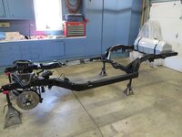
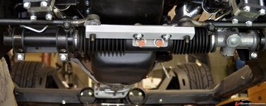
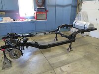
There might be some joy in locating at in a rear steer setup. Here is a C3 with steering box and associated steering arms.
1981-C3-Corvette-Frame-Restored-Suspension.jpg

You can note the position the rack "might" fit into, but then need to swap sides of the uprights and configure the tie rods. Also not having the motor mounts (motro plates) makes some space available too. But, I've re-tapered the arms (on the uprights) for the ball joint to mount from above. Could conduct some major surgery and fix that I suppose.

The Roadster shop has a pretty cool setup that would be helpful - front steer low, c5 etc for a C3 But that is a whole frame solution...

I think I'd want to move a bit of weight forward - just aft of 50/50 now, and fuel etc will move further aft.

Ahhh, ain't hot roddin' fun!?

Cheers - Jim
 
Jim,

Swapping spindles designed for front steer that have fixed steering arms has its own set of problems. For anywhere near correct Ackermann, the front steer uprights have the steering arms angled outboard so a line drawn from the outer tie rod end through the upper ball-joint-to-lower ball-joint line points in the general direction of the center of the rear end. Uprights designed for rear steer have the steering arms angled inboard to point in the same direction (toward the center of the rear end). Using the C7 spindles with their fixed steering arms on a rear steer set-up will give you some really wonky Ackermann. There are spindles, like the SpeedTech ATS spindles, that are made for late Corvette bearings and brakes that have removable steering arms. I built the steering arms out of 7075 aluminum to achieve the steering ratio and Ackermann I wanted. I think you are better off sticking with front steer with the C7 spindles.

Pappy

Edit: It occurs to me that if you opt to go rear steer with the C7 uprights, the tie rod extenders you built actually pull the pivot points for the outboard end of the tie rods into about the correct position.

View attachment 2283
 
Last edited:
There might be some joy in locating at in a rear steer setup. Here is a C3 with steering box and associated steering arms.
1981-C3-Corvette-Frame-Restored-Suspension.jpg

You can note the position the rack "might" fit into, but then need to swap sides of the uprights and configure the tie rods. Also not having the motor mounts (motro plates) makes some space available too. But, I've re-tapered the arms (on the uprights) for the ball joint to mount from above. Could conduct some major surgery and fix that I suppose.

The Roadster shop has a pretty cool setup that would be helpful - front steer low, c5 etc for a C3 But that is a whole frame solution...

I think I'd want to move a bit of weight forward - just aft of 50/50 now, and fuel etc will move further aft.

Ahhh, ain't hot roddin' fun!?

Cheers - Jim

Respectfully, I'm not following why you would want to purposely move weight forward given the present f/r ratio you have.
 
Jim,

Swapping spindles designed for front steer that have fixed steering arms has its own set of problems. For anywhere near correct Ackermann, the front steer uprights have the steering arms angled outboard so a line drawn from the outer tie rod end through the upper ball-joint-to-lower ball-joint line points in the general direction of the center of the rear end. Uprights designed for rear steer have the steering arms angled inboard to point in the same direction (toward the center of the rear end). Using the C7 spindles with their fixed steering arms on a rear steer set-up will give you some really wonky Ackermann. There are spindles, like the SpeedTech ATS spindles, that are made for late Corvette bearings and brakes that have removable steering arms. I built the steering arms out of 7075 aluminum to achieve the steering ratio and Ackermann I wanted. I think you are better off sticking with front steer with the C7 spindles.

Pappy

Edit: It occurs to me that if you opt to go rear steer with the C7 uprights, the tie rod extenders you built actually pull the pivot points for the outboard end of the tie rods into about the correct position.

View attachment 2283

I'm not familiar with C7 knuckles. Do they have "centered" spindles, or are the spindles offset rearward like C4 knuckles?
 
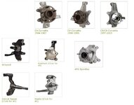
The C7 is very similar to the C5/6 - except for the casting:
12695c693f4e376df.jpg

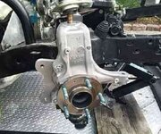
Here is the C7. The steering is 'forward'
12695d18cfaea1614.jpg

For today, I'm planning on keeping the front steer setup, and opting to use the steering gear reverse box. It is on order and should be in next week. A bit of complication to locate it, but all do-able.

Regarding CG. My "Guestimator Spreadsheet" was off a bit, and the scales showed the truth, such as it is. The old 50/50 is a nice bench-racing tale, and closer to 40/60 often seen as the better choice. Then there is always the balance of Center of Rotation vs CG, which you can futz with a bit. I've been reviewing a bit of these details and am planning on using the square setup and aero to get more or less grip at either end. The R&P is a heavy piece of gear for sure, but other bits I've yet to attach at the rear are too;, Setrab oil cooler/radiator etc for transaxle, fuel pumps, filters, blah, blah. If I need to add some grip aft, then its bigger tires (wider) and staggered, etc.

Its bloody hot outside today - Heat Stress Warning. I may get a few minutes on the brakes today. Will post as it goes.


Cheers - Jim
 
My concern with the grand am rack is the CTO... When I had one configured for rear steer, the bracket that I made to position the tie rods in the correct location/length had some deflection about the center two mounting bolts. That was with street tires and only ~5* of castor. With sticky, wide tires and (assuming) 6+* of castor I wonder if that rack might be prone to fail earlier under the abuse I hope youre going to put it the car through.

Excellent to see some progress!
 
Chris -

Did the bracket fail or the rack? Yeah, I plan on it seeing some ause, and the 1/4" steel bar stock is just there to position bits and make sure I can steer to push/roll on/off the trailer.

Here is one that is well sized, but if the rack is the failure prone item, this wouldn't matter:
maxresdefault.jpg

Threat of tropical depression this weekend - so clean up the garage and push the car into the clean spot.

Back to it.

Cheers - Jim
 
My concern with the grand am rack is the CTO... When I had one configured for rear steer, the bracket that I made to position the tie rods in the correct location/length had some deflection about the center two mounting bolts. That was with street tires and only ~5* of castor. With sticky, wide tires and (assuming) 6+* of castor I wonder if that rack might be prone to fail earlier under the abuse I hope youre going to put it the car through.

Excellent to see some progress!

I was concerned with the torque on that bracket and the two mount bolts when I did my Grand Am setup. The tie rods attach to those bolts in the Grand Am so there is basically no torque on that center mount.

When I was laying this out, I found that the rack input shaft was usually rotated up about 45 degrees. That causes two problems. It makes it impossible to use 2 U joint couplers with the same angle an one of those angles is greater than 15 degrees. Also I found that rotating the input shaft down (to 30 degrees) moved the CTO mount bolts towards the tie rod ends. That reduced the offset and therefore the torque on that mount.

I also machined these mount holes and they are zero clearance with the bolts.

45988a0b35ede5.jpg
 
BBShark -

Once again a great hint! Thanks, I got the C4 bit and its a perfect fit on the rack. I will make it into a short stub and add a u-joint to the DD shaft. Easy-peasy.

Also, the steering gear reversing box arrived from Coleman just now too. Much faster than if I setup to make my own. It will let me keep the front steer. Now to copy the mount for the CTO as you built!

With the car in the garage, and a break in the heat, I might get the front end done (soon). Brakes, etc.

Cheers - Jim
 
I am well overdue on an update. I will try and keep it “organized.”

  • Elvira – most germane to the forum
  • My Sports Racer
  • Other vehicles
ELVIRA:

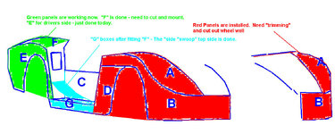
Here are the panel diagrams I made to help focus my fiberglass efforts:
A BLUELINE OF PARTS LABELED.jpg


Of these, A through F are completed. Front wheel openings are made (although several inches smaller to allow for exact placement. The Front/Nose section will be mounted in 3 pieces, Left and Right fenders, and the center section. This will reduce the weight when removing segments for access to the engine bay, a request of my crew. I cut out the center section and it was surprisingly heavy – much body work there, so a sheet metal spacer/insert may suffice for testing (when that happens).
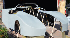
nose - n- tail.jpg
The rear section is currently a single piece, and I am considering making the rear window (it is a fastback 78 – recall) hinged like the later 82 version(?).

With the nose and tail mounted on saw horses in the drive, it looks very foreshortened but with the cover over it – actually looks like a car – a very wide car.


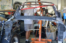
moving bridcage.jpg
The C-panels are built but not yet mounted to the much chopped birdcage. The outside segments of the G-Panels are laid and together with the “ramp” will form the tunnels on each side. The shape of the “ramp” is a low-Reynolds number/High Lift Sellig airfoil. To put these pieces together I had to move the center section into the “shop” (garage).

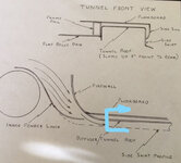
This diagram gives an idea of where the side "boxes/tunel/skirts are headed - but not at 8 degrees:

skirts + tunnel.jpg

The chassis waits for effort, while the weather has been cooperative, I’ve made much boy work, laying panels, building fenders, prep, and prime.

SPORTS RACER:

All this effort is being accomplished because the SR is “on the block.” It has been sold to a very interested party, who will be coming to pick up in a weeks. He gets a very good deal, I clean a bunch of stuff out of the garage, and a space in the driveway, or the storage lot. As part of the deal he gets the trailer too, so now I’m in the market for one now.

OTHER VEHICLES:


The Solstice got some new shoes, went with KUMHO ECSTAs and lower profile. Also installed a Stage 2 Tune, new CAI, Cat-DEL, and new charge tubes. [Next up would be a bigger Intercooler.] I already have the backbone on the chassis, and the rear end mod. Now I need to sort out a front spreader bar. Downside is our local SCCA Region (Gulf Coast) only does AX, so that will be the weekend entertainment, but at least its close. Interestingly, the Turbo-Solstice is classed AS/P, which puts it in with the Corvettes and Camaros. We’ll plan on towing to a few Track Nites when we get a new trailer. Don’t like having to fetch a tow truck if “5h!t happens.”

TOW VEHICLE:

The Nissan Xtera has been a good one and hauls the SR very well. But dealing with hotels, meals, etc has become a drag, so we are flying out this weekend to pick up a new (to us) Tow Vehicle. Not as spiffy as what Super-Buick-Guy has planned, but short enough to fit in the driveway and hauls 8000 # with its 6.0L Chevy engine. Plus it is “home away from home:” when trackside. It will be small, and well less than 1/2 the space of our sailboat [did I say SOLD?}rt in MA to get.jpg

I’ll close this short update with a shot of the current stable:


Stable in the Drive.jpg

This will have to "do" for a bit. A delivery trip with the R-Van from NE US to FL is next. Then no doubt some attention to it. Sort out the rolling stock and get the center section 'glassed, inner fenders sorted out, fit the nose-n-tail, build an interior finish IFS, wiring, steering, engine, fuel, brakes. Just a few items.

Cheers - Jim
 
OK - A restart!
I'll rewind a bit.


1. Yes, the Solstice is a blast to drive. I put som lower profile tires on, a dramatic (ok Stage 2) tune and improved turbo air and CAT. I want to AX it, but she says - NO. Last time you scratched the paint.
2. Sold the Sports Racer and trailer. Miss 'em both - but the purpose was to get the 'vette going. Even so I got a bit sidetracked with the RV-thing - but now;

BACK TO WORK!

The uprights I was going to use, were just too "funky." Even on the rear, I was less than satisfied. Would have done the trick I suppose, but not what I was looking for. Using the LG lowered hubs designed for the rear on the front was not inspiring either. [I Shoulda-coulda kept the Giovanni and been done with it - ahhh - Hindsight.] So at long last,. I bit the bullet and spent a good part of last winter rethinking and drawing a set of uprights.

Because I am "wedded" to using 15 inch wheels, the real challenge was fitting the package into the rims. That was the major reason for going to a clean sheet. I also wanted a "big-or grunty" a set of calipers I could squeeze in. There are some trade offs working within those constraints, but I think it will be acceptable.

Next I convinced my machinist buddy to do the work. He took some time 'cause he "fits" the job in and always has a very fair deal for me - so acceptable.

Now with the weather improving, the garage is warm enough to do a bit of work. So, I got started today. My machinist code named the uprights "The Bricks." The name will be obvious when you see them. I spent no time minimizing weight in the design (yet). The objective is get this assembled, get it run through its paces and on the track. Interim time can be spent redesigning (learning FEA in Solidworks is high on the to-do list), then refining and rebuilding. You might say these are the MiG version of an upright.

Today's order of business was:
1. Sweep the floor for pictures​
2. Mount the Uprights, then the brake calipers and rotors​
3. Mount the wheels.​
4. Dry fit the inner fender "sweeps"​
5. Check for clearance at full lock​
6. Slip the Airbox in place to check access and clearance to the shocks​

Here is the driver's side hub with wheel mounted and caliper in place. The upright is designed to be compatible with 2 varients of Wilwood radial mounts. The side not in use is used for mounting the steering arm. [Not welded up yet.] They can be swapped side to side for front or rear steer as needed. Ackerman will be built into the mount that is securred to the upright. The Nail is a quick reference for the welds yet to come...
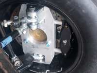

01 Drivers Hub.jpg

The passenger's side upright in place. The Tapped holes are to mount the radial mount calipers. Because I may use the rear steet Steerroids, the calipers will be in the leading position.
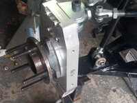

03 Pax Hub 2.jpg

The "sweeps" have been built for over a year now. But now it was time to do a clearance check on the "sweeps" at max left rotation (full lock?):
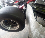

04 clearance at Full Lock.jpg

I also did a clearance at full right turn: (pretty good view of Pushrod suspension setup too.)
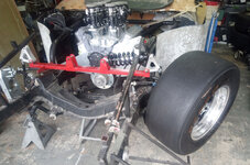
05 clearance at Full Lock RT Turn.jpg
Next slide the Airbox in place


06 Airbox in place.jpg

And, check clearance and access to shock dual adjust confirmed.
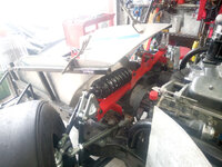
07 Airbox clearance check - final.jpg

The design work was all done in CAD, so fairly confident everything would fit:
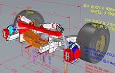


CAD of IFS.jpg

I only got the wheel/caliper/rotor installed on the driver's side today. Working shims on the pushrod setup took a bit longer than anticipated.
But satisfactory with no rattles/vibrations/squeeks and moves freely. (Well, not with the springs in place, 500#/in, so I test without springs.) A key design element of the pushrod setup, is the bridge. It mounts between the upper A-Arm and the mounts. A key feature is it is also is a spreader bar. Not adjustable - but soild and will hold the geometry under load.

I expect these next tasks will somewhat follow this path: I'm looking to bear down tomorrow through this next week:
7. Mount Passenger's front wheel (caliper and rotor)​
8. Finish assembly of Passenger rear hub/upright assembly​
9. Mount Rear wheels​
10. Secure rear shocks -- this has been bugging me.​
Should I weld the mounts to the roll cage - or can I drill through the mount and mechanically fasten?​
11. Lower to garage floor - First time in a Long time!​
12. "Scale" the chassis, check/measure all suspension points [Data input to Suspension Analysis]​
Not exact numbrers, but something close enough for "feel good."​
13. Raise chassis and put back on Jackstands Very Happy I have the Quick Jack system!
14. Sort out steering rack mount (use on-hand Steeroids parts? - TBD)​
Then start fabrication as needed. I have materials on hand for the tierods, so no long lead items there.​
15. Position steering shaft (Setup will be "rear steer" for the Steeroids rack)​

That looks like a few days effort, but wait - more to come!
16. Resolve any potential header/dry sump interference I need to place the priming pump and tank, then all the hose work to be done.​
Headers are going to be a bug-a-boo. I have a couple of choices from the scrap heap - the Stahl 360 and Schoenfeld 180s. I think neither will fit, so that will create some realighment of tasks and potential delays.​
17. Build and install Brake lines. Locate and install brake system pump.​
18. Build and install fuel lines, fuel pump, sump, etc.​
19. Locate battery box. Prelay electrical cabling. Prefit Electrodyne system. Lay in data power, dash instrumentation, lighting, fusing, active aero, etc.​
20. Complete Dry Sump install 4 port system (need to work intake galley pickup)​
21. Mount Airbox​
22. Install radiator, plumbing, and fans​
23. Build/Fit foam/glass airbox/radiator fairings​
23. Layout belly pan, splitter, and diffuser​
24. Build firewall​
25. Design/fab dash​
26. Cockpit floor, tunnel, and rear firewall - Pedal box, connections to Brakes and Throttle, Shifter (700R-4 Full manual/Reverse)​
27. Seat(s) and belts​
28. Back to Bodywork​

Clearly the frame will need some touch-up paint, but that is later no doubt.

ONWARD!
 
  • Like
Reactions: rtj
I'll check in the morning - I'm shut down right now - but made some good progress today too.

Tomorrow morning I'll set it up and lower the chassis and birdcage to the floor. (YIPPIE!!!)
I'll measure then and try and video the lowering. (That sounds dangerous...)

The purpose tomorrow is to weigh and scale the chassis + the bits that are on and in it.
Its been a while since I've used the Quick Jack, it so might need to freshen the hydraulics fluid, etc.
I am anticipating a few "bumps" in the road.

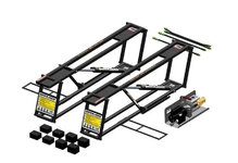
A neat aspect of these hydraulic jack systems, is you can mount the stands on a wall vertically, then stow the hydraulic pack on a shelf.
Much smaller than a floor jack. (Image not mine - but a good representation)
quick jack stowed.jpg
And you can put it under the car at a right angle if needed. Maybe that length is useful?
Those blocks you see in the advert - are on my system movable and stackable. You set them in place, and adjust to the chassis lift point.
Then Lift. They are "keyed" to fit together and not slip apart.

Folks have added rollers to make it easier to get under the car - but not used to move the car while on it - (booo).

Cheers - Jim
 
I have a QJ 5000XL. It has a 60" lift length, but I also bought the 66" extenders because 60" was not long enough for the C8. 60" works great on the Viper and the C1.

Great to see you back on Elvira!
 
Thanks Pappy!

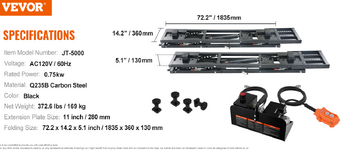
Here is a snap of a similar unit with my measures on it:quick jack measures.jpg

The range of lifting points are shown as 30 - 44 inches. Overall width is 11". Fully compressed (down) is just at 4"

I can hit the 'vette OK, and previously the Sports Racer which had a full belly pan and weighed just over 1200#. Its ride height was a problem, so drove it up on ramps then did the lift. The Solstice is just under the 3500# limit at 3000#. It lifts on "pucks" like newer model Vettes do (I guess).

As I understand - the extensions fit on top of the exixting QJ. I expect they are of the same gauge tubing and plate. I would espect "indexing" pieces (blocks?) to keep from shifting out of the lifting "pockets." Hope that helps.

Cheers - Jim
 
Last edited:

Latest posts

Back
Top